FIR filter overview
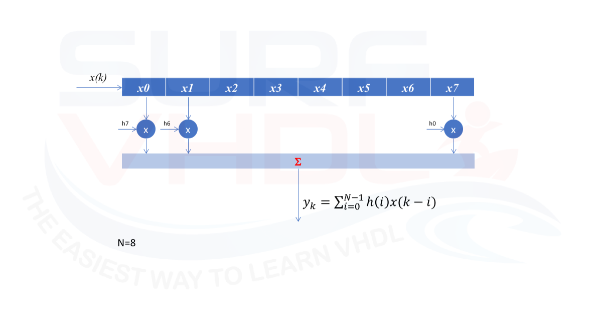
When we implement an FIR filter in FPGA or ASIC the major cost in terms of area resources derives from the multiplier units required for coefficient multiplication. Depending on the frequency response of the filter, the number of coefficients (or filter taps) could become large.
As clear from an FIR filter architecture in Figure 1 the number of multiplier operations is equal to the number of taps, for a long filter the area required will be demanding.
FIR architecture possible optimization
For applications where the sampling speed is low, or where the speed ratio between the system clock versus the filter output speed requirement we can adopt a resource sharing strategy.
Another optimization possibility can be adopted when the coefficients of the filter can be expressed as powers-of-two. In this case, the multiplication can be performed with a shift and add operations.
If you need to refresh the FIR architecture you can take a look to this post: http://surf-vhdl.com/how-to-implement-fir-filter-in-vhdl/
Here we want to address a very interesting FIR architecture optimization that we can adopt when we can take advantage of some hypothesis on input data.
Shaping filter for modulator system
In this post, we talk about the implementation of an ASK modulator: http://surf-vhdl.com/implement-digital-ask-modulator-vhdl/
In the modulator, the output shaping filter could be very demanding in terms of area, but an optimization could be implemented.
If the modulation is a quadrature modulation such as ASK, BPSK, QPSK, the input symbols to the matching output filter will be of this form:
- +A
- –A
where A is the amplitude of the modulated signal.
In this case, we can set A=1, so the input symbols to the output matched filter will be +/-1.
Just to clarify, in Figure 2 is reported an example of QPSK modulation where the amplitude of in-phase and quadrature channel is +/-1:
- “00” I=+1, Q=+1
- “01” I=-1, Q=+1
- “11” I=-1, Q=-1
- “10” I=1, Q=-1

in this case, the input pipe to the filter will contain always +/-1.
As the first optimization, the multiplier they can be replaced with a change sign of the coefficient.
This can be a starting optimization but in this post,
we want to go further.
Let’s optimize even more our filter.
Implementing the memory mapped filter architecture
As said before, the input filter pipe will get the +/-1 as the input value.
We can codify:
- +1 => ‘0’
- -1 => ‘1’
For sake of simplicity, let the filter length just 4 taps. For an input filter pipe of 4 let’s see how the input filter pipe looks like for all possible input pattern in Figure 3

 index |   x0    x1    x2    x3  => +/-1 coded
____________________________________________________________
     0 |    0     0     0     0   |     1     1     1     1
     1 |    0     0     0     1   |     1     1     1    -1
     2 |    0     0     1     0   |     1     1    -1     1
     3 |    0     0     1     1   |     1     1    -1    -1
     4 |    0     1     0     0   |     1    -1     1     1
     5 |    0     1     0     1   |     1    -1     1    -1
     6 |    0     1     1     0   |     1    -1    -1     1
     7 |    0     1     1     1   |     1    -1    -1    -1
     8 |    1     0     0     0   |    -1     1     1     1
     9 |    1     0     0     1   |    -1     1     1    -1
    10 |    1     0     1     0   |    -1     1    -1     1
    11 |    1     0     1     1   |    -1     1    -1    -1
    12 |    1     1     0     0   |    -1    -1     1     1
    13 |    1     1     0     1   |    -1    -1     1    -1
    14 |    1     1     1     0   |    -1    -1    -1     1
    15 |    1     1     1     1   |    -1    -1    -1    -1
Can you imagine what could be the next step?
Right! A Look-Up-Table
for any of the input pattern, we can use the input filter pipeline as the address of a LUT that contains the output filter value.
                 INPUT                   Impulse response
 index |    x0    x1    x2    x3   |    15    47    51   -12    |  sum(h*x)
__________________________________________________________________________
     0 |      1     1     1     1  |    15    47    51   -12    |    101
     1 |      1     1     1    -1  |    15    47    51    12    |    125
     2 |      1     1    -1     1  |    15    47   -51   -12    |     -1
     3 |      1     1    -1    -1  |    15    47   -51    12    |     23
     4 |      1    -1     1     1  |    15   -47    51   -12    |      7
     5 |      1    -1     1    -1  |    15   -47    51    12    |     31
     6 |      1    -1    -1     1  |    15   -47   -51   -12    |    -95
     7 |      1    -1    -1    -1  |    15   -47   -51    12    |    -71
     8 |     -1     1     1     1  |   -15    47    51   -12    |     71
     9 |     -1     1     1    -1  |   -15    47    51    12    |     95
    10 |     -1     1    -1     1  |   -15    47   -51   -12    |    -31
    11 |     -1     1    -1    -1  |   -15    47   -51    12    |     -7
    12 |     -1    -1     1     1  |   -15   -47    51   -12    |    -23
    13 |     -1    -1     1    -1  |   -15   -47    51    12    |      1
    14 |     -1    -1    -1     1  |   -15   -47   -51   -12    |   -125
    15 |     -1    -1    -1    -1  |   -15   -47   -51    12    |   -101
As you can see, the filter implementation is reduced to a 1-bit shift register and a LUT.
We could not ask for more!
Of course, there is a problem. As clear the LUT dimension will depend on the filter length in an exponential way:
- filter length =3 => LUT length = 8
- filter length =4 => LUT length = 16
- filter length =N => LUT length = 2^N
for a 16 taps filter, we get 2^16 = 65536 (64K) LUT length.
It is a big deal!
But we can do some optimization even in this case.
Let’s see what if the filter length is 8 as in Figure 4
In this case, the LUT length will be 2^8 = 256

We can rearrange the filter architecture as in Figure 5. Instead of using the entire filter pipe of 8 bit, we can break into 2×4 bit pipe and add the output of the LUT.
This is very similar to the classical filter architecture that you can see here: http://surf-vhdl.com/how-to-implement-fir-filter-in-vhdl/
The result is that the filter LUT is no more 256, but 2 x16.

More general if we need a filter length of N, we can implement the same filter using two 2 LUT of dimension 2^(N/2)
in the case of 8, we have 2 x 2^4=16 instead of 2^8=256,
I think it could be a good optimization.
Filter LUT implementation
In the previous section, we addressed how to optimize a matched filter architecture for an ASK modulator. Now we will understand how to compute the LUT value starting from a given filter impulse response.
We will use Matlab/Octave code to compute the LUT coefficient.
The first thing we need is the filter input pattern as the binary vector that we will use as LUT address.
Now we remap this 0/1 vector as +/-1 where
- 0=> +1
- 1=>-1
this coding will give the 2’complement encoding for free.
In fact in 2’complement representation (see the post: http://surf-vhdl.com/binary-number-representation/ ) the MSB in the sign of the number
- ‘0’ => positive or zero
- ‘1’ => negative
Using this coding pattern, the input to the filer will be the MSB of the mapper. Of course, also the mapper will be simplified using only 1-bit coding.
Now that we get all the possible input pattern to the filter, let’s compute the LUT values for each LUT address.
If you remember the FIR filter equation

the LUT value can be computed as a simple matrix by vector multiplication where the input matrix xM represents all the possible value of the input pipe and h is the filter impulse response. Here below the Matlab/Octave script:
fileLen = 8;
% generate the address matrix
d = (0:2^fileLen-1)';
t = de2bi(d,[],2,'left-msb');
[d t]

% convert address matrix in +/-1
xM = 1-2*t

% filter coefficient
h = [15  47 51 -12]

% create the LUT for the filter
Lut = mtimes(xM,h')
Now we have all the information to implement the VHDL code for the filter.
VHDL implementation of a simplified Modulator filter
Here below you can find the VHDL implementation of the modulator filter implemented with LUT.

The filter is implemented as 4 taps filter. Here below a possible VHDL implementation for the FIR-LUT filter:
library ieee;
use ieee.std_logic_1164.all;
use ieee.numeric_std.all;

entity filter_lut4 is
port (
  i_clk          : in  std_logic;
  i_rstb         : in  std_logic;
  i_data_ena     : in  std_logic;
  i_data         : in  std_logic;  -- 1 bit input
  o_data_valid   : out std_logic;
  o_data         : out std_logic_vector(7 downto 0));
end filter_lut4;

architecture rtl of filter_lut4 is
constant C_FILTER_LEN            : integer := 4;
constant C_LUT_BIT               : integer := 8;
---------------------------------------------------------------------------------------------------
type t_lut is array (0 to (2**C_FILTER_LEN)-1) of integer range -(2**C_LUT_BIT) to (2**C_LUT_BIT)-1;

constant C_LUT                           : t_lut := (
   101 ,	 125 ,	  -1 ,	  23 ,	   7 ,	  31 ,	 -95 ,	 -71 ,	  71 ,	  95 ,	 -31 ,	  -7 ,	 -23 ,	   1 ,	-125 ,	-101 );

signal r_data_pipe                         : std_logic_vector(C_FILTER_LEN-1 downto 0);
signal r_data_ena                          : std_logic;

begin

p_data : process(i_clk,i_rstb)
begin
  if(i_rstb='0') then
    r_data_pipe    <= (others=>'1');
    r_data_ena     <= '0';
    o_data         <= (others=>'0');
    o_data_valid   <= '0';
  elsif(rising_edge(i_clk)) then
    o_data_valid   <= r_data_ena;
    r_data_ena     <= i_data_ena;
    if(i_data_ena='1') then
      r_data_pipe    <= i_data&r_data_pipe(r_data_pipe'length-1 downto 1);
    end if;
    o_data         <= std_logic_vector(to_signed(C_LUT(to_integer(unsigned(r_data_pipe))),C_LUT_BIT));
  end if;
end process p_data;

end rtl;
In the next example, there is reported the VHDL implementation of an 8 taps filter cascading the two previous 4 taps filter as in Figure 5.
library ieee;
use ieee.std_logic_1164.all;
use ieee.numeric_std.all;

entity filter_lut4x2 is
port (
  i_clk          : in  std_logic;
  i_rstb         : in  std_logic;
  i_data_ena     : in  std_logic;
  i_data         : in  std_logic;  -- 1 bit input
  o_data_valid   : out std_logic;
  o_data         : out std_logic_vector(8 downto 0));
end filter_lut4x2;

architecture rtl of filter_lut4x2 is
constant C_FILTER_LEN            : integer := 4;
constant C_LUT_BIT               : integer := 8;
---------------------------------------------------------------------------------------------------
type t_lut is array (0 to (2**C_FILTER_LEN)-1) of integer range -(2**C_LUT_BIT) to (2**C_LUT_BIT)-1;

constant C_LUT1                           : t_lut := (
   101 ,	 125 ,	  -1 ,	  23 ,	   7 ,	  31 ,	 -95 ,	 -71 ,	  71 ,	  95 ,	 -31 ,	  -7 ,	 -23 ,	   1 ,	-125 ,	-101 );
constant C_LUT2                           : t_lut := (
   -14 ,	 138 ,	  18 ,	 170 ,	-122 ,	  30 ,	 -90 ,	  62 ,	 -62 ,	  90 ,	 -30 ,	 122 ,	-170 ,	 -18 ,	-138 ,	  14 );

signal r_data_pipe1                         : std_logic_vector(C_FILTER_LEN-1 downto 0);
signal r_data_pipe2                         : std_logic_vector(C_FILTER_LEN-1 downto 0);
signal r_data_ena                           : std_logic;

signal w_addr_lut1                          : integer range 0 to ((2**C_FILTER_LEN)-1);
signal w_addr_lut2                          : integer range 0 to ((2**C_FILTER_LEN)-1);

begin
w_addr_lut1     <= to_integer(unsigned(r_data_pipe1));
w_addr_lut2     <= to_integer(unsigned(r_data_pipe2));

p_data : process(i_clk,i_rstb)
begin
  if(i_rstb='0') then
    r_data_pipe1   <= (others=>'1');
    r_data_pipe2   <= (others=>'1');
    r_data_ena     <= '0';
    o_data         <= (others=>'0');
    o_data_valid   <= '0';
  elsif(rising_edge(i_clk)) then
    o_data_valid   <= r_data_ena;
    r_data_ena     <= i_data_ena;
    if(i_data_ena='1') then
      r_data_pipe1    <= i_data&r_data_pipe1(r_data_pipe1'length-1 downto 1);
      r_data_pipe2    <= r_data_pipe1(0)&r_data_pipe2(r_data_pipe2'length-1 downto 1);
    end if;
    o_data         <= std_logic_vector(to_signed(C_LUT1(w_addr_lut1),o_data'length) + to_signed(C_LUT2(w_addr_lut2),o_data'length));
  end if;
end process p_data;

end rtl;
Notice that the output filter dynamics depends on how many bits we quantize the filter coefficients. In this post, we did not address the filter design and quantization.
An example of FIR filter coefficient quantization is given in this post: http://surf-vhdl.com/how-to-quantize-fir-coefficient/
Simulation of filter VHDL code
In Figure 7 is presented the simulation of the 8 taps FIR filter output in Figure 5 compared with the reference generated using Matlab/Octave code here below.

As clear in the transitory part, i.e. when the number of input data is less than the filter length, there is a mismatch between the reference output and VHDL output. In this simulation the filter length is 8 symbols, so the mismatch can be at least 8 output filtered symbols. In order to facilitate the check of the filter matching, is reported an “error_flag” in yellow.
Notice that if we want to match all the filter output we need to initialize the Matlab filter as the VHDL implementation filter.
Layout of VHDL simplified matching filter
Figure 8 reports the RTL view of the 8 taps filter described in the previous paragraph. As clear the filter structure is very straightforward. The layout reports the area resources are of very few cells. The same filter implemented using the classical architecture is much more demanding.

Conclusion
In this post, we addressed the VHDL implementation of a digital filter using a LUT approach.
This filter architecture is very in terms of area and timing resources.
Like all good things, this architecture has the drawbacks that the input data can be only +/-1.
Even if this restriction, we can use this optimization in a wide modulator filter implementation if the modulation can be reported as an amplitude like modulation.
An example was given for a QPSK modulation.
References
[2] https://www.mathworks.com/
[4] https://www.gnu.org/software/octave/
[5] “DSP Architecture Design Essentials”, Authors: Marković, Dejan, Brodersen, Robert W.
[6] https://en.wikipedia.org/wiki/Finite_impulse_response
It is a wonderful implementation!!! I’m sure about this!
Thank you, Antonio!
Thank you for this course.
Please, would you like explain the case “where the sampling speed is low, or where the speed ratio between the system clock versus the filter output speed requirement we can adopt a resource sharing strategy”.
For example, if the ADC sampling rate is 1 MHz and your processing clock frequency is 100 MHz, for every input ADC sample you have 100 clock cycles available. In this case, you can implement a 100 taps filet using just 1 multiplier. In the next future, I will write a post on this topic.
ciao
Thank you very much for the short and clear explanation
You are welcome!
Hi…
I Need More more information about this chapter…
what do you need to know?