How to implement a digital filter without multiplier

FIR filter overview

When we implement an FIR filter in FPGA or ASIC the major cost in terms of area resources derives from the multiplier units required for coefficient multiplication. Depending on the frequency response of the filter, the number of coefficients (or filter taps) could become large.

As clear from an FIR filter architecture in Figure 1 the number of multiplier operations is equal to the number of taps, for a long filter the area required will be demanding.

Figure 1 – Classic FIR architecture

Read More

How to Realize a FIR Test Bench in FPGA

Debugging an FIR in FPGA

The VHDL, and other hardware description languages such as Verilog, SistemVerolog and so on, allow us to simulate your digital design in a very accurate way.

If you write a good VHDL code after the simulation you are very confident that your VHDL design will work as it should. When you go to silicon often there are problems and you should debug your VHDL code.

Here you can find some of the common issues you have during the test of VHDL design on FPGA. The modern FPGAs allow the user to enable debug facility inside the silicon using a proprietary debug tool very like an embedded logic state analyzer.

Using Altera Quartus II you can enable the Signal Tap Analyzer or the equivalent using Xilinx Chipscope.

Figure 1 – FIR Test Bench using Terasic DE0 board

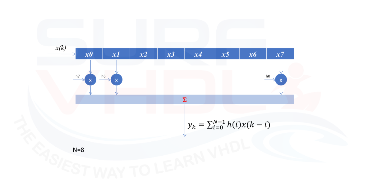
In this post, we are going to see an example of how to debug an FIR using the push button and the seven-segment display of a typical demo board with an FPGA, implementing a complete VHDL test bench that will be implemented in a Terasic DE0 board.

Read More

Compute exp(x) in FPGA using VHDL

Where the exponential functions are used?

The exponential functions are used mainly where non-linear behavior are present. An example of exp(x) is given in Figure 1. Since we are dealing with an exponential behavior, in the normal use of the function, the value of the exponent is range limited. For example, your algorithm could use 0<x<1, or -1<x<1 and so on. It is very unlikely you should deal with x in the entire real range when you implement a signal processing algorithm in FPGA.

Figure 1 – exp(x) function

Read More

Implement Digital ASK Modulator in VHDL

Introduction to ASK modulation

In this post, we are going to understand the fundamental of Digital Modulation from the basic. An example of VHDL implementation of a digital modulator is given at the end of the post.
Digital Modulation technique is very important in the telecommunication world and substituted the analog modulation since is more flexible and can be implemented if a small and cheap electronics. We will focus on the implementation of the digital modulator.

Figure 1 – Example of digital modulator Architecture

The basic implementation of Amplitude-shift keying (ASK) is a form of amplitude modulation that represents digital data as variations in the amplitude of a carrier wave. Read More

How to Implement a sinusoidal DDS in VHDL

What is a sinusoidal Direct Digital Synthesis (DDS)?

The Direct Digital Synthesis (DDS) is a method of producing an analog waveform using a digital device. In this post, we are going to illustrate how to generate digitally a sine-wave using a digital device such as FPGA or ASIC.

Figure1 – DDS typical architecture

The sine/cosine wave generated can be used inside your digital design in order to perform digital up/down frequency conversion. Read More

How to Implement NCO in VHDL

 What is an NCO?

An NCO is the acronym of Numerically Controlled Oscillator.

Figure 1 – NCO basic architecture

Basically, it is implemented with an accumulator which adds a constant value FCW (Frequency Control Word). The accumulator wrap around every time it reaches its maximum value. For example, if the maximum value is 15 (4-bit accumulator) and the FWC = 4, the accumulator will count: Read More

How to Implement a Pipeline Multiplier in VHDL

Multiplier in modern FPGA

In the modern FPGA, the multiplication operation is implemented using a dedicated hardware resource. Such dedicated hardware resource generally implements 18×18 multiply and accumulate function that can be used for efficient implementation of complex DSP algorithms such as finite impulse response (FIR) filters, infinite impulse response (IIR) filters, and fast fourier transform (FFT) for filtering and image processing applications etc.

The Multiplier-Accumulator blocks has a built-in multiplier and adder, which minimizes the fabric logic required to implement multiplication, multiply-add, and multiply-accumulate (MACC) functions. Implementation of these arithmetic functions results in efficient resource usage and improved performance for DSP applications. In addition to the basic MACC function, DSP algorithms typically need small amounts of RAM for coefficients and larger RAMs for data storage. Read More

How to Implement FIR Filter in VHDL

FIR Filter Introduction

Finite Impulse Response (FIR) filters are characterized by a time response depending only on a given number of the last samples of the input signal. For a causal discrete-time FIR filter of order N, each value of the output sequence is a weighted sum of the most recent input values:


fir_filter_equation


where:

  • x[n] is the input signal,
  • y[n] is the output signal,
  • N is the filter order; a Nth-order filter has (N+1) terms on the right-hand side
  • bi is the value of the impulse response at the i’th instant for 0<= i <=N of a Nth-order FIR filter. If the filter is a direct form FIR filter then is also a coefficient of the filter (see Figure1).

Read More