

FIR Filter Introduction
Finite Impulse Response (FIR) filters are characterized by a time response that depends only on the last N samples of the input signal. For a causal discrete-time FIR filter of order N, each value of the output sequence is a weighted sum of the most recent input values:
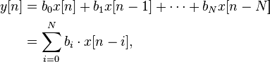
where:
- x[n] is the input signal,
- y[n] is the output signal,
- N is the filter order; an Nth-order filter has (N+1) terms on the right-hand side
- bi is the value of the impulse response at the i-th instant for 0 <= i <= N of an Nth-order FIR filter. If the filter is a direct form FIR filter then is also a coefficient of the filter (see Figure1).
This computation is also known as discrete convolution.
On Wikipedia FIR web-page, you can find further information on FIR design theory.
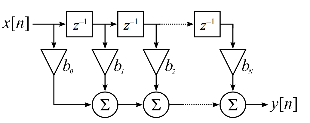
Figure 1 – FIR Filter direct form implementation
FIR Filter Hardware Architecture
Here we will see how to implement a FIR filter architecture in an FPGA or ASIC using VHDL.
Figure 2 shows an example of a 4-tap FIR direct form that can be simply coded in VHDL. In Figure 2, the input x(n) and the coefficient bi are 8-bit signed.
After the filter coefficient multiplication, the multiplier output dynamic will be 8+8=16 bits.
When multiplying an N-bit and an M-bit number, the output dynamic of the multiplication result is (N+M) bits. When performing an addition, the number of bits of the result is incremented by 1. The FIR filter architecture of Figure 2 can be easily extended to a length greater than 4.
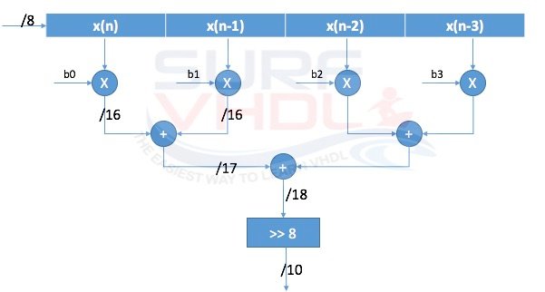
4-tap FIR Filter hardware architecture example
Interactive Simulator: 4-Tap FIR Filter (Float vs Fixed-Point)
Explore how coefficient values and quantization (bit-width) affect the filter's output. This bridges the gap between ideal math (Floating-point) and VHDL hardware implementation (Fixed-point).
1. Input Signal
2. Filter Coefficients (Taps) & Quantization
FIR Filter Design VHDL Code
Below is the VHDL code for the FIR filter design of Figure 2. The VHDL code implements a low-pass FIR filter with 4 taps, an 8-bit input, and 8-bit coefficients.
library ieee;
use ieee.std_logic_1164.all;
use ieee.numeric_std.all;

entity fir_filter_4 is
port (
  i_clk        : in  std_logic;
  i_rstb       : in  std_logic;
  -- coefficient
  i_coeff_0    : in  std_logic_vector( 7 downto 0);
  i_coeff_1    : in  std_logic_vector( 7 downto 0);
  i_coeff_2    : in  std_logic_vector( 7 downto 0);
  i_coeff_3    : in  std_logic_vector( 7 downto 0);
  -- data input
  i_data       : in  std_logic_vector( 7 downto 0);
  -- filtered data
  o_data       : out std_logic_vector( 9 downto 0));
end fir_filter_4;

architecture rtl of fir_filter_4 is

type t_data_pipe      is array (0 to 3) of signed(7  downto 0);
type t_coeff          is array (0 to 3) of signed(7  downto 0);

type t_mult           is array (0 to 3) of signed(15    downto 0);
type t_add_st0        is array (0 to 1) of signed(15+1  downto 0);

signal r_coeff              : t_coeff ;
signal p_data               : t_data_pipe;
signal r_mult               : t_mult;
signal r_add_st0            : t_add_st0;
signal r_add_st1            : signed(15+2  downto 0);

begin

p_input : process (i_rstb,i_clk)
begin
  if(i_rstb='0') then
    p_data       <= (others=>(others=>'0'));
    r_coeff      <= (others=>(others=>'0'));
  elsif(rising_edge(i_clk)) then
    p_data      <= signed(i_data)&p_data(0 to p_data'length-2);
    r_coeff(0)  <= signed(i_coeff_0);
    r_coeff(1)  <= signed(i_coeff_1);
    r_coeff(2)  <= signed(i_coeff_2);
    r_coeff(3)  <= signed(i_coeff_3);
  end if;
end process p_input;

p_mult : process (i_rstb,i_clk)
begin
  if(i_rstb='0') then
    r_mult       <= (others=>(others=>'0'));
  elsif(rising_edge(i_clk)) then
    for k in 0 to 3 loop
      r_mult(k)       <= p_data(k) * r_coeff(k);
    end loop;
  end if;
end process p_mult;

p_add_st0 : process (i_rstb,i_clk)
begin
  if(i_rstb='0') then
    r_add_st0     <= (others=>(others=>'0'));
  elsif(rising_edge(i_clk)) then
    for k in 0 to 1 loop
      r_add_st0(k)     <= resize(r_mult(2*k),17)  + resize(r_mult(2*k+1),17);
    end loop;
  end if;
end process p_add_st0;

p_add_st1 : process (i_rstb,i_clk)
begin
  if(i_rstb='0') then
    r_add_st1     <= (others=>'0');
  elsif(rising_edge(i_clk)) then
    r_add_st1     <= resize(r_add_st0(0),18)  + resize(r_add_st0(1),18);
  end if;
end process p_add_st1;

p_output : process (i_rstb,i_clk)
begin
  if(i_rstb='0') then
    o_data     <= (others=>'0');
  elsif(rising_edge(i_clk)) then
    o_data     <= std_logic_vector(r_add_st1(17 downto 8));
  end if;
end process p_output;


end rtl;
The FIR filter is implemented fully pipelined; there is a registration stage at the output of each multiplication or addition.
The output dynamic of the FIR filter is 10 bits (i.e. it does not cover the full output dynamic range). The selection r_add_st1(17 downto 8) extracts the upper 10 bits from the 18-bit accumulator, discarding the 8 least significant bits. This truncation is a trade-off between output width and precision: the lower bits represent finer quantization steps that are not needed for the target application.
The VHDL code of the FIR filter can be implemented in either an ASIC or an FPGA. This implementation guarantees full speed for the FIR filter.
Figure 3 shows RTL viewer of Intel Quartus II for the FIR filter VHDL example code above
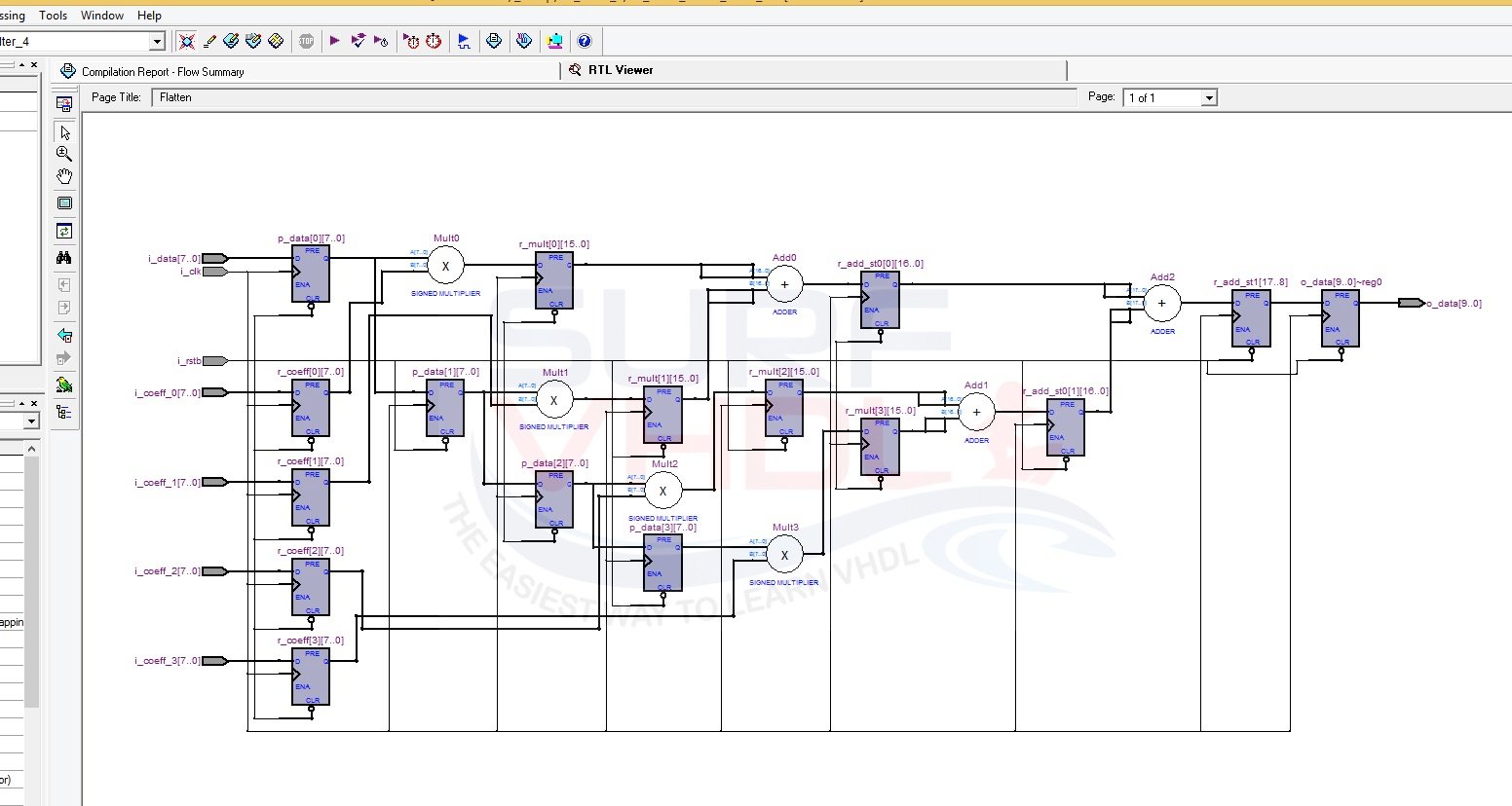
Figure 3 – FIR Filter Quartus II RTL viewer
How to Implement FIR Filter in VHDL
Get the complete VHDL code from this article.
If you appreciated this post, please share it with your friends.
If you need to contact us, please write to: surf.vhdl@gmail.com