The errors occur in burst
When we establish a communication between two or more devices we are prone to errors.
In this post, we can see how to prevent errors using a coding technique like Reed-Solomon coding. There are a lot of coding techniques in the literature.
But the only data coding is not enough for a good prevention of communication error.
The encoders/decoders work fine on a “sparse” error condition. In a communication channel errors occur in bursts.
Think about it.
When you have a perturbation over a channel, it persists on the channel for a certain amount of time.
During the perturbation on the communication link, the number of bits involved will be proportional to the speed of the link: higher is the link speed, higher will be the consecutive number of bits that can be affected.
So, what could be a solution to this issue?
The solution is very simple, just distribute the consecutive transmitted bit over time so that a single channel perturbation cannot act on a consecutive bit.
This technique is named “interleaving“. Of course, in the receiver side, we need to reassemble the distributed bit in order to recover the correct bitstream with the complementary interleaving algorithm i.e. de-interleaving the data stream.
Interleaver technique
An interleaver simply commutate the bit order a communication link, in order to distribute the bitstream to prevent burst error on a communication channel.
Generally, in a digital communication link, the data stream is packetized.
The simplest interleaver is the row-column interleaver.

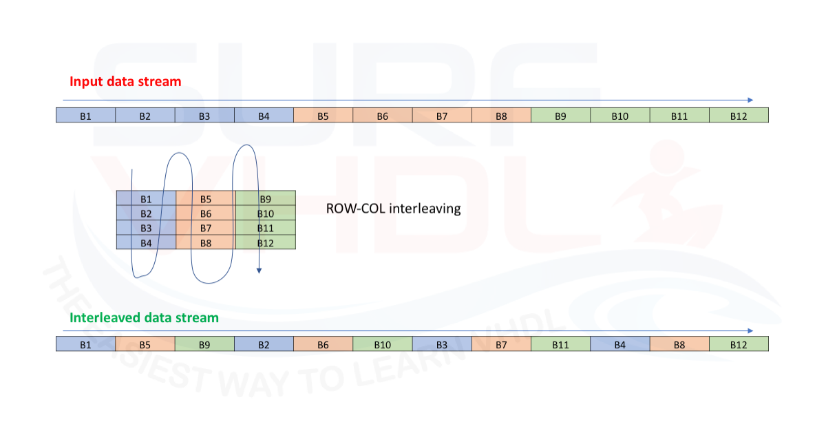
Just to understand. Let the data packet 12 bits. If we transmit the packet as it is, we have the data stream as in the top of Figure 1.
Now let’s interleave the data in a row-col way. Figure 1 should clarify.
In this case, we have that the consecutive bits are separated by a distance of 4 bit of the packed, so the encoder/decoder block should work better.
The bit separation, i.e. the interleaving distance depends on Link speed, Channel model, etc.
Convolutional Interleaver
A little bit more complicated interleaver is the convolutional interleaver. Such interleaver is used in the DVB-S standard.
The convolutional interleaver works on a continuous data stream.
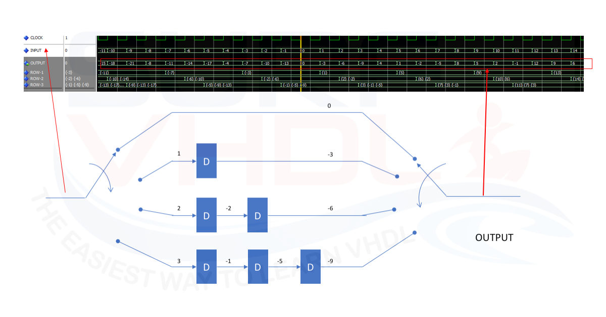
The convolutional interleaver architecture is reported in Figure 2. Here we can see a simplified architecture just to understand the behavior.

Each ROW is delayed by a different number of a clock cycle.
As clear from the simulation, if the data packet starts from index zero, the interleaved data output of the current data packet N contains data of the N-1 data packet.
Hence the term convolutional, because the current data packet contains data from the previous one.
DVB-S convolutional interleaver
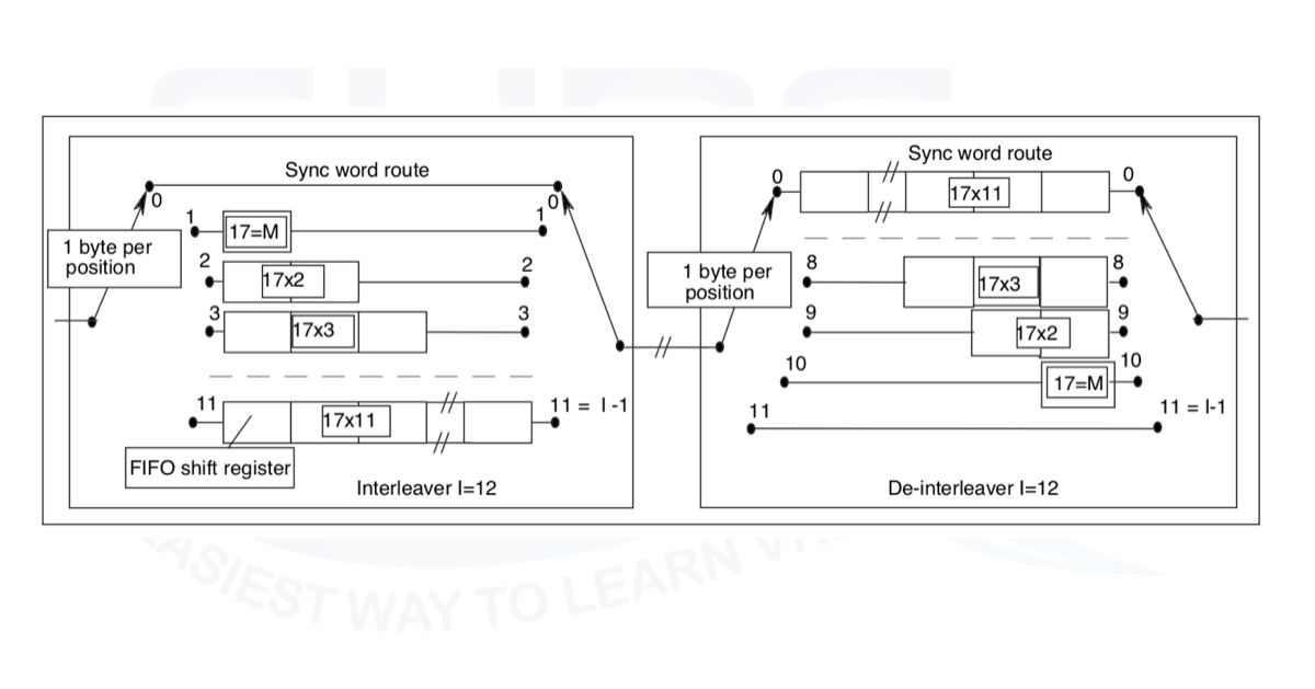
The DVB-S standard implements a convolutional interleaver with the same structure as in the previous section but with 12 ROWs with different delay values on each row.
The structure derives directly from the data packet size. In this post, we don’t want to analyze the reasons for such architecture. If you want to understand the DVB-S standard you can read the specification following the links reported in the reference section.
The figure of the architecture is derived directly from the DVB-S standard. The interleaver structure is realized with a FIFO like architecture. In the next section, we will see a possible VHDL implementation of the convolutional interleaver

VHDL implementation of Convolutional interleaver
From Figure 3 the VHDL implementation is straightforward:
library ieee;
use ieee.std_logic_1164.all;
use ieee.numeric_std.all;

entity conv_interleaver is
generic (
  N                : integer:=8); -- number of I/O bit  port (
port (
  i_clk                                   : in  std_logic;
  i_rstb                                  : in  std_logic;
  i_sync_reset                            : in  std_logic;
  i_data_enable                           : in  std_logic;
  i_data                                  : in  std_logic_vector(N-1 downto 0);
  o_data_valid                            : out std_logic;
  o_data_out                              : out std_logic_vector(N-1 downto 0));
end conv_interleaver;

architecture rtl of conv_interleaver is

type p_row_fifo is array(integer range <>) of std_logic_vector(N-1 downto 0);

signal r_counter_enc                                      : integer range 0 to 11;

signal p_row_1         : p_row_fifo(0 to 17*1 - 1);
signal p_row_2         : p_row_fifo(0 to 17*2 - 1);
signal p_row_3         : p_row_fifo(0 to 17*3 - 1);
signal p_row_4         : p_row_fifo(0 to 17*4 - 1);
signal p_row_5         : p_row_fifo(0 to 17*5 - 1);
signal p_row_6         : p_row_fifo(0 to 17*6 - 1);
signal p_row_7         : p_row_fifo(0 to 17*7 - 1);
signal p_row_8         : p_row_fifo(0 to 17*8 - 1);
signal p_row_9         : p_row_fifo(0 to 17*9 - 1);
signal p_row_10        : p_row_fifo(0 to 17*10- 1);
signal p_row_11        : p_row_fifo(0 to 17*11- 1);

begin

p_interleaver_control : process(i_clk,i_rstb)
begin
  if(i_rstb='0') then
    r_counter_enc    <= 0;
    o_data_valid     <= '0';
  elsif(rising_edge(i_clk)) then
    o_data_valid     <= i_data_enable;
    if(i_sync_reset='1') then
      r_counter_enc    <= 0;
    elsif(i_data_enable='1') then
      if(r_counter_enc=11) then
        r_counter_enc    <= 0;
      else
        r_counter_enc    <= r_counter_enc + 1;
      end if;
    end if;
  end if;
end process p_interleaver_control;

p_interleaver : process(i_clk)
begin
  if(rising_edge(i_clk)) then
    if(i_data_enable='1') then
      case r_counter_enc is
        when 1   => o_data_out  <= p_row_1 (p_row_1 'length-1); p_row_1  <= i_data&p_row_1 (0 to p_row_1 'length-2);
        when 2   => o_data_out  <= p_row_2 (p_row_2 'length-1); p_row_2  <= i_data&p_row_2 (0 to p_row_2 'length-2);
        when 3   => o_data_out  <= p_row_3 (p_row_3 'length-1); p_row_3  <= i_data&p_row_3 (0 to p_row_3 'length-2);
        when 4   => o_data_out  <= p_row_4 (p_row_4 'length-1); p_row_4  <= i_data&p_row_4 (0 to p_row_4 'length-2);
        when 5   => o_data_out  <= p_row_5 (p_row_5 'length-1); p_row_5  <= i_data&p_row_5 (0 to p_row_5 'length-2);
        when 6   => o_data_out  <= p_row_6 (p_row_6 'length-1); p_row_6  <= i_data&p_row_6 (0 to p_row_6 'length-2);
        when 7   => o_data_out  <= p_row_7 (p_row_7 'length-1); p_row_7  <= i_data&p_row_7 (0 to p_row_7 'length-2);
        when 8   => o_data_out  <= p_row_8 (p_row_8 'length-1); p_row_8  <= i_data&p_row_8 (0 to p_row_8 'length-2);
        when 9   => o_data_out  <= p_row_9 (p_row_9 'length-1); p_row_9  <= i_data&p_row_9 (0 to p_row_9 'length-2);
        when 10  => o_data_out  <= p_row_10(p_row_10'length-1); p_row_10 <= i_data&p_row_10(0 to p_row_10'length-2);
        when 11  => o_data_out  <= p_row_11(p_row_11'length-1); p_row_11 <= i_data&p_row_11(0 to p_row_11'length-2);
        when others   => o_data_out  <= i_data  ;
      end case;
    end if;
  end if;
end process p_interleaver;

end rtl;
The 11 FIFOs are implemented as shift-register. Of course, this is not the optimal solution since we need a huge number of flip-flops.
A RAM-based solution can be adopted, using a dual port ram that emulates the FIFO behavior.
Another solution can be implemented using the FIFO delay line implemented with shift-register with the shift-register implemented as FIFO. You can find an example in this post.
Conclusion
In this post, we addressed the interleaver technique used in digital communication in order to mitigate the occurrences of burst errors on the channel link.
In the post, we have been proposed a VHDL implementation of the DVB-S convolutional interleaver.
References
[2] https://www.mathworks.com/
[4] https://www.gnu.org/software/octave/
[6] https://en.wikipedia.org/wiki/Burst_error-correcting_code
[8] “ECSS-E-50-01A – Space data links – Telemetry synchronization and channel coding”
Great… As usual.
I have a question for You (and the whole blog) : how to implement in a efficient way a row column interleaver?
Tz
A great website and a great post.
thanks for you’re time.
You are welcome!
how set the simulation factor? ex) rstb,sync etc.
what do you mean with “simulation factor”?