How to implement a shift register in VHDL

I wrote many posts on different VHDL topics. Many of them deal with quite a complex concept.

Some days ago, I realized that I didn’t write anything “simple” dealing with the basic hardware building block.

I realized that since I received many email and telegram messages asking me to explain them some line of VHDL code. These lines are relative to a simple shift register implementation.

Sometimes what is simple for you, is not for other people!

In this post, I would like to propose three different ways of implementing a shift register in VHDL.

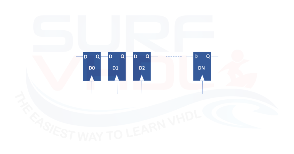
First of all, let’s review what is a shift register. It could be represented with a series of flip flop connected in series, where the output of one flip-flop is the input of the other.

In Figure 1 you can see a visual representation.

Figure 1 shift register architecture example

As stated before, there are at least three different ways to describe such hardware structure in VHDL. The three descriptions are totally equivalent.

Read More

How to implement convolutional encoder in VHDL

Why we need an encoder


In the communication link, the noise, multipath effect and all the other effects that affect the communication can induce errors on the communication link. In this post, we already addressed the topic introducing the Reed-Solomon encoder.

Here we want to exploit another encoder widely used in communication link: Convolutional Encoder.

After a brief introduction to the Convolutional encoder, we will go to see the thing that interests us the most, I mean the VHDL implementation of a Convolutional Encoder.

Figure 1 – Example of a communication channel

Read More

How to implement a convolutional interleaver

The errors occur in burst


When we establish a communication between two or more devices we are prone to errors.

In this post, we can see how to prevent errors using a coding technique like Reed-Solomon coding. There are a lot of coding techniques in the literature.

But the only data coding is not enough for a good prevention of communication error.

The encoders/decoders work fine on a “sparse” error condition. In a communication channel errors occur in bursts.

Think about it.

When you have a perturbation over a channel, it persists on the channel for a certain amount of time.

During the perturbation on the communication link, the number of bits involved will be proportional to the speed of the link: higher is the link speed, higher will be the consecutive number of bits that can be affected.

So, what could be a solution to this issue?

Read More

How to implement a digital filter without multiplier

FIR filter overview

When we implement an FIR filter in FPGA or ASIC the major cost in terms of area resources derives from the multiplier units required for coefficient multiplication. Depending on the frequency response of the filter, the number of coefficients (or filter taps) could become large.

As clear from an FIR filter architecture in Figure 1 the number of multiplier operations is equal to the number of taps, for a long filter the area required will be demanding.

Figure 1 – Classic FIR architecture

Read More

How to implement a Reed-Solomon Encoder in VHDL

What is an RS-Encoder


When you want to transfer information from a source to a target, you want to be sure that such information is transferred without errors.

When you transfer an information through a communication channel, such information will be prone to errors.

In order to minimize or eliminate the number of errors during the information transmission, we can adopt some error correction strategies.

Figure 1 – Satellite communication corrupted by the link channel noise

Such strategies are named FEC, i.e. Forward Error Correction. As you can imagine, nothing is for free. If you want to guarantee an error-free transmission you need to “pay” in terms of transmission bandwidth and transmitter/receiver complexity.

Any error correction strategy needs to transmit much more information than the minimum required, in order to allow the receiver to recognize if the received information is correct and, in case of error, provide to correct the errors.

Without entering in the error correction field theory, very complex and wide argument, here we want to address one possible error correction algorithm.

There are two main approaches to implement Error- Correction Coding:

  • Block Coding: the symbol stream is divided into a block and coded.
  • Convolution Coding: convolution operation is applied to the symbol stream.

Read More

How to implement Galois multiplier in VHDL

Why Galois field

The Galois fields are mainly used in cryptography and error correction algorithm.

If you never deal with Galois field, at the beginning the topic could seem very hard to understand. In this post we want to address the galois field theory from the practical application point of view.

We will review:

  • the Galois arithmetic notation, just to understand how to interpret the equation
  • add/sum operation in Galois field
  • multiplier in Galois field

Figure 1 – Galois multiplier in GF(2^m)

the third point maybe is the most difficult to understand.

It might put noses out of joint after reading this post because I will not be very rigorous in the representation of the theory of the Galois fields. This post wishes to give you a practical implementation starting point for your VHDL design using Galois arithmetic.

I put a lot of references at the bottom of this post that will help you to go deeper in the Galois field theory if you are really interested in it.

Read More

How to interface a FPGA processor with VHDL peripheral

FPGA and Processor

The modern FPGAs implement microprocessor internally either as soft-processor or hard-processor. The soft-processor is intended as microprocessor implemented into the FPGA starting from a VHDL/Verilog code.

So, in this case, the processor is synthesized using the current FPGA technology (and layout tool).

Soft-processors have the advantages to be portable into a different technology. LEON processor is a soft-processor example that is realized as a stand-alone chip and can be integrated into a VHDL design as IP.

Figure 1 – FPGA-SoC Processor to peripheral interface

The Hard-processor is intended as a dedicated FPGA silicon area that implements the processor.

As you can understand, it is dependent on the FPGA are you using. For example, Intel Cyclone V SoC family implements a dual-core processor ARM-Cortex A9.

Another example is the Xilinx ZYNQ that implement different processor families, ARM-Cortex A9, Arm Cortex-A53.

When we use a processor in FPGA (hard-processor or soft-processor) sometimes we need to interface such processor with our custom peripheral implemented in VHDL (or Verilog or other custom implementation). In this case, we could experience different issues in the processor – peripheral interfacing:

  • A bus of different size
  • Different interface signals
  • Synchronization during READ/WRITE operation

Read More

How to implement a digital MUX in VHDL

Before reading the post, if you need the VHDL code example of the Digital MUX, just put your email in the box you find in the post. There is no need to post a comment asking me for the code 🙂
If you don’t receive the email, please check your SPAM folder, enjoy!

What is a MUX?

When we implement a digital hardware architecture, we often need to select an input to our logic between several different inputs. This selection logic is called digital multiplexer or MUX.

We name it digital multiplexer, to distinguish it from an analog multiplexer. An analog multiplexer implements the same function as digital MUX selecting the source of a signal from different analog source instead of digital.

As clear in Figure1, a MUX can be visualized as an n-way virtual switch whose output can be connected to one of the different input sources. On the left side of the Figure1, you can see the typical MUX representation. The number near the input ports indicates the selector value used to route the selected input to the output port.

Figure-1 N-Way MUX

Read More

How to implement an LFSR in VHDL

What is an LFSR

A linear-feedback shift register (LFSR) is a shift register whose input bit is a linear function of its previous state. We can use this type of functions in many application such as counters, crypto, ber-meter, CRC generation, scrambling/descrambling algorithm, test application and so on

An LFSR of length N can generate 2^N-1 different states where the values look like pseudo-random values.

There are two different types of LFSR implementation the FIBONACCI and the GALOIS implementation as in Figure1. The LFSR implementations are equivalent.

Figure 1 – LSFR generic architecture


If we are implementing the LFSR in hardware, the Galois implementation is much more efficient since use two input XOR function and the XOR function is implemented between two consecutive registers. Read More