What is an LFSR
A linear-feedback shift register (LFSR) is a shift register whose input bit is a linear function of its previous state. We can use this type of functions in many application such as counters, crypto, ber-meter, CRC generation, scrambling/descrambling algorithm, test application and so on
An LFSR of length N can generate 2^N-1 different states where the values look like pseudo-random values.
There are two different types of LFSR implementation the FIBONACCI and the GALOIS implementation as in Figure1. The LFSR implementations are equivalent.
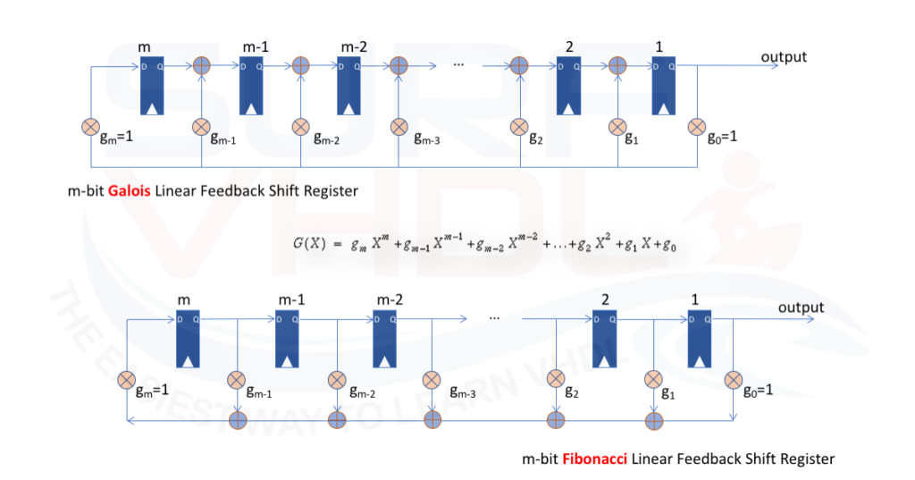
If we are implementing the LFSR in hardware, the Galois implementation is much more efficient since use two input XOR function and the XOR function is implemented between two consecutive registers.
In the Fibonacci implementation, the XOR ports are cascaded so in this case, the delay due to the consecutive ports can affect the timing performances of the circuit. Vice versa we can use the Fibonacci implementation in the modern FPGA taking advantage of the LUT architecture that can implement the XOR matrix as multiport XOR function.
The LFSR can be implemented also using XNOR primitive function instead of XOR.
In this post, we focus on Galois LFSR architecture, all the consideration can be ported to the Fibonacci architecture.
VHDL implementation of LFSR
The VHDL implementation of an LFSR is very simple starting from its graphical representation.
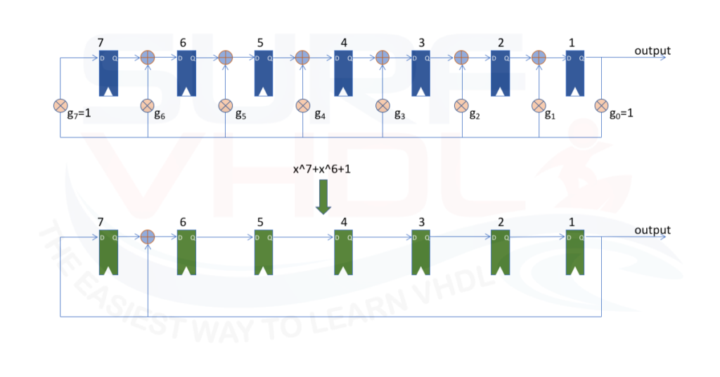
In Figure 2 is reported a 7-bit LFSR using the generator polynomial
g(x)= x^7+x^6+1
starting from the generic LFSR structure, the VHDL Galois implementation is straightforward as in Figure 2:
library ieee;
use ieee.std_logic_1164.all;

entity lfsr_7_plain is
port (
  i_clk           : in  std_logic;
  i_rstb          : in  std_logic;
  i_sync_reset    : in  std_logic;
  i_seed          : in  std_logic_vector (6 downto 0);
  i_en            : in  std_logic;
  o_lsfr          : out std_logic_vector (6 downto 0));
end lfsr_7_plain;

architecture rtl of lfsr_7_plain is

signal r_lfsr           : std_logic_vector (7 downto 1);

begin
o_lsfr  <= r_lfsr(7 downto 1);

p_lfsr : process (i_clk,i_rstb) begin
  if (i_rstb = '0') then
    r_lfsr   <= (others=>'1');
  elsif rising_edge(i_clk) then
    if(i_sync_reset='1') then
      r_lfsr   <= i_seed;
    elsif (i_en = '1') then
      r_lfsr(7) <= r_lfsr(1);
      r_lfsr(6) <= r_lfsr(7) xor r_lfsr(1);
      r_lfsr(5) <= r_lfsr(6);
      r_lfsr(4) <= r_lfsr(5);
      r_lfsr(3) <= r_lfsr(4);
      r_lfsr(2) <= r_lfsr(3);
      r_lfsr(1) <= r_lfsr(2);
    end if;
  end if;
end process p_lfsr;

end architecture rtl;
In the VHDL implementation of the LFSR, we can also introduce the synchronous reset to initialize the seed of the LFSR.
It is possible to write the same VHD code for the LFSR in a more compact and realize a parametric VHDL code for LFSR implementation way as below:
library ieee;
use ieee.std_logic_1164.all;

entity lfsr is
generic(
  G_M             : integer           := 7          ;
  G_POLY          : std_logic_vector  := "1100000") ;  -- x^7+x^6+1
port (
  i_clk           : in  std_logic;
  i_rstb          : in  std_logic;
  i_sync_reset    : in  std_logic;
    i_seed          : in  std_logic_vector (G_M-1 downto 0);
    i_en            : in  std_logic;
    o_lsfr          : out std_logic_vector (G_M-1 downto 0));
end lfsr;

architecture rtl of lfsr is
signal r_lfsr           : std_logic_vector (G_M downto 1);
signal w_mask           : std_logic_vector (G_M downto 1);
signal w_poly           : std_logic_vector (G_M downto 1);

begin
o_lsfr  <= r_lfsr(7 downto 1);

w_poly  <= G_POLY;
g_mask : for k in G_M downto 1 generate
  w_mask(k)  <= w_poly(k) and r_lfsr(1);
end generate g_mask;

p_lfsr : process (i_clk,i_rstb) begin
  if (i_rstb = '0') then
    r_lfsr   <= (others=>'1');
  elsif rising_edge(i_clk) then
    if(i_sync_reset='1') then
      r_lfsr   <= i_seed;
    elsif (i_en = '1') then
      r_lfsr   <= '0'&r_lfsr(G_M downto 2) xor w_mask;
    end if;
  end if;
end process p_lfsr;

end architecture rtl;
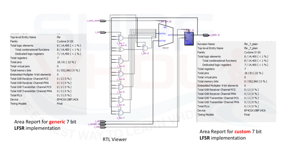
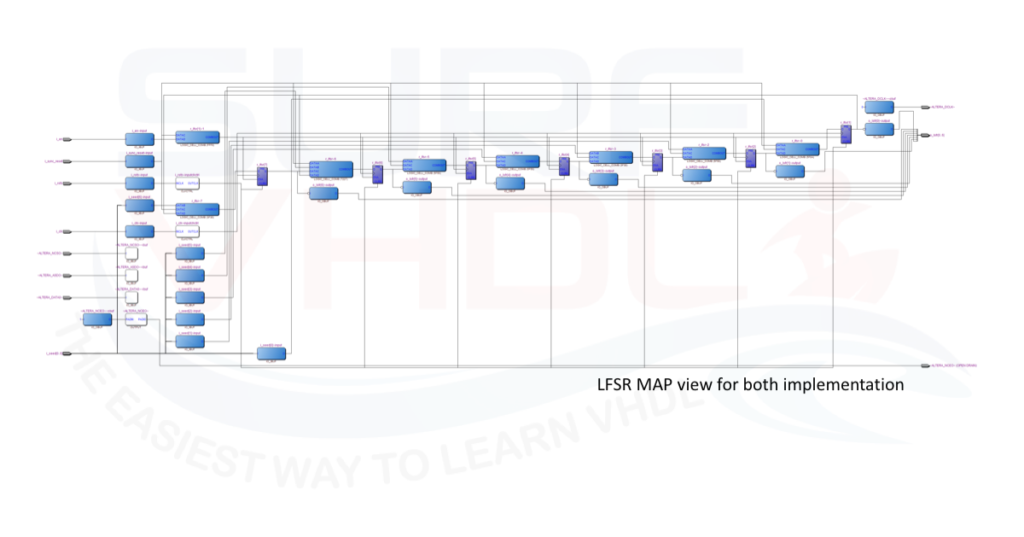
It is clear that the unrolled representation of the LFSR is much more readable, but the implementation is the same as clear in FIGURE where it is reported the output of the layout of the two VHDL code of LFSR implemented above.
VHDL implementation result of LFSR
In order to evaluate the VHDL code implementation of the LFSR in custom LFSR realization and generic LFSR implementation, Figure3 shows the simulation of the two implementations of 7-bit LFST implementation running in parallel. As clear the output of the custom LFSR implementation “lfsr_plain” in Figure3 and the output of the simulation of VHDL code of generic LFSR implementation “lfsr” is identical.
In order to check if both LFSR VHDL coded are processed in the same way by the synthesizer, a trial layout has been implemented using Quartus II.
Both VHDL codes have been implemented on the same Cyclone IV giving the same results on
Area report, timing report, MAP report and technology map report as in Figure 4

Conclusion
In this post, we addressed the Galois implementation of a Linear Feedback Shift Register (LFSR) in VHDL. In the implementation, we used the XOR architecture. A similar architecture can be used with the XNOR primitive function. In the references section, you can find useful links for the XOR and XNOR polynomial generator.
When you have to implement an LFSR, you should pay attention to the numbering convention of the shift-register position. Some articles number the shift register as 0 to M, others use the opposite convention M down to 0. Of course, the generator polynomial must take into account the numbering convention.
Here below you can find a set of a primitive polynomial that you can use in the parametric LFSR VHDL implementation reported above:
constant C_POLY2               : std_logic_vector( 2 downto 1):= "11";  -- x^2+x+1
constant C_POLY3               : std_logic_vector( 3 downto 1):= "110";  -- x^3+x^2+1
constant C_POLY4               : std_logic_vector( 4 downto 1):= "1100";  -- x^4+x^3+1
constant C_POLY5               : std_logic_vector( 5 downto 1):= "10100";  -- x^5+x^3+1
constant C_POLY6               : std_logic_vector( 6 downto 1):= "110000";  -- x^6+x^5+1
constant C_POLY7               : std_logic_vector( 7 downto 1):= "1100000";  -- x^7+x^6+1
constant C_POLY8               : std_logic_vector( 8 downto 1):= "10111000";  -- x^8+x^6+x^5+x^4+1
constant C_POLY9               : std_logic_vector( 9 downto 1):= "100010000";  -- x^9+x^5+x^4+1
constant C_POLY10              : std_logic_vector(10 downto 1):= "1001000000";  -- x^10+x^7+1
constant C_POLY11              : std_logic_vector(11 downto 1):= "10100000000";  -- x^11+x^9+1
constant C_POLY12              : std_logic_vector(12 downto 1):= "111000001000";  -- x^12+x^11+x^10+x^4+1
constant C_POLY13              : std_logic_vector(13 downto 1):= "1110010000000";  -- x^13+x^12+x^11+x^8+1
constant C_POLY14              : std_logic_vector(14 downto 1):= "11100000000010";  -- x^14+x^13+x^12+x^2+1
constant C_POLY15              : std_logic_vector(15 downto 1):= "110000000000000";  -- x^15+x^14+1
constant C_POLY16              : std_logic_vector(16 downto 1):= "1011010000000000";  -- x^16+x^14+x^13+x^11+1
constant C_POLY17              : std_logic_vector(17 downto 1):= "10010000000000000";  -- x^17+x^14+1
constant C_POLY18              : std_logic_vector(18 downto 1):= "100000010000000000";  -- x^18+x^11+1
constant C_POLY19              : std_logic_vector(19 downto 1):= "1110010000000000000";  -- x^19+x^18+x^17+x^14+1
References
[1] https://en.wikipedia.org/wiki/Cyclic_redundancy_check#Designing_CRC_polynomials
[3] http://www.xilinx.com/support/documentation/application_notes/xapp052.pdf
[4] https://www.xilinx.com/support/documentation/application_notes/xapp210.pdf
[5] https://www.altera.com/content/dam/altera-www/global/en_US/pdfs/literature/manual/stx_cookbook.pdf
[6] https://en.wikipedia.org/wiki/Linear-feedback_shift_register
Error in Line 23:
o_lsfr <= r_lfsr(7 downto 1);
should be
o_lsfr <= r_lfsr(G_M downto 1);
good! Thank you
ciao
What is the function of w_mask? And the purpose of the AND with r_lfsr(1). I understand the polynomial but not why we create w_mask by anding with only the last value in r_lfsr
w_mask implement the generator polynomial
I badly needed the VHDL code of BCH code’s generator Polynomial.
I seems that the value 0 is never generated by lfsr_7_plain (checked on several thousand of generated values). Is it normal ?
yes, if the zero is a singularity for the LSFR, I mean the it gets stuck
Hey just to clarify. The i_seed is the input to the LFSR?.
Any other tips for using this for a CRC?
Also can you please share the tb.
Cheers,
Joe
i_seed is the starting value for the LFSR, the seed
Is the test bench available for this? If so can it be sent to me please.
Hello, great article. Please can you email me the test bench.
Please can you send me the test bench