FPGA and Processor
The modern FPGAs implement microprocessor internally either as soft-processor or hard-processor. The soft-processor is intended as microprocessor implemented into the FPGA starting from a VHDL/Verilog code.
So, in this case, the processor is synthesized using the current FPGA technology (and layout tool).
Soft-processors have the advantages to be portable into a different technology. LEON processor is a soft-processor example that is realized as a stand-alone chip and can be integrated into a VHDL design as IP.
The Hard-processor is intended as a dedicated FPGA silicon area that implements the processor.
As you can understand, it is dependent on the FPGA are you using. For example, Intel Cyclone V SoC family implements a dual-core processor ARM-Cortex A9.
Another example is the Xilinx ZYNQ that implement different processor families, ARM-Cortex A9, Arm Cortex-A53.
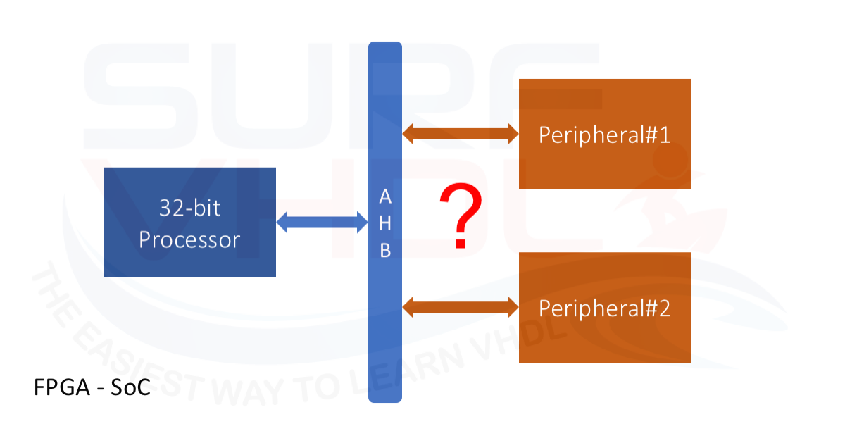
When we use a processor in FPGA (hard-processor or soft-processor) sometimes we need to interface such processor with our custom peripheral implemented in VHDL (or Verilog or other custom implementation). In this case, we could experience different issues in the processor – peripheral interfacing:
- A bus of different size
- Different interface signals
- Synchronization during READ/WRITE operation
A possible solution to FPGA processor interface
In order to find the optimal solution for FPGA internal processor interface to a custom peripheral, we need first to understand which the interface constraints are:
- High-Data transfer rate;
- Simple interface configuration with READ/WRITE configuration registers
Of course, the proposed solutions are dependent on the FPGA and memory bus we are using. In this post, I only want to give a general overview to address the possible solutions.
Fast data transfer rate
If we need a fast data transfer rate between the processor and the peripheral using a custom interface, we can implement a bridge between the processor and our module using two different approaches:
- Shared Dual port memory
- FIFO interface
Both solutions allow decoupling the processor clock domain and the peripheral clock domain. In order to synchronize data exchange, an interrupt-based synchronization approach can be adopted.
Shared Dual port memory
When the processor needs to send data to peripheral, writes data un the dual port memory write area, then signals the data ready event using a dedicated sync line.
The same approach can be used from the peripheral side when the processing is completed and data need to be sent to the processor. The peripheral will write its data result on the dual port memory read area dedicated to the peripheral results and send an interrupt to the processor.
A possible architecture is in Figure 2

FIFO interface
In the FIFO interface approach, we need to implement two FIFOs as in Figure 3. Since the processor is master on the BUS, we refer as FIFO-TX and FIFO-RX as FIFOs relative to processor write-process and processor read-process as in
- FIFO-TX: processor writes the data to be sent to the peripheral.
- FIFO-RX: processor read data from the peripheral.

As you can see, the FIFO architecture implements also the control data flow.
Let’ analyze the processor write process:
On the processor side, the processor checks the (quasi) full flag of the FIFO-TX
- FIFO_TX_FULL is low: (assuming high when the FIFO-TX is quasi-full) processor write data into FIFO
- FIFO_TX_FULL is high: processor the peripheral to read from FIFO before writing another data
On the peripheral side, the peripheral checks the empty flag of the FIFO-TX.
- If empty flag is low (assuming the empty flag high when no data is present in the FIFO) the peripheral will read the data
Processor read process.
We can connect the FIFO-RX empty flag to a processor interrupt or poll the flag into software in order to trigger the read of the data process from the FIFO when the peripheral writes data into it.
As clear the FIFO-FLAGs can be used to implement a flow control between the processor and peripheral.
Slow data transfer rate
Some processor-peripheral interfaces do not require fast data exchange rate. A typical application is when we need to configure some register of the peripheral or read out the peripheral status. In this case, the interface can be implemented as a memory mapped like GPIO interface (see Figure 4).

As clear in this case, if the processor and peripheral use different clock, we need to take into account designing an asynchronous data exchange interface. This interface should consider resynchronization strobes in order to guarantee the correct data exchange.
In the FIFO or dual-port memory interfaces architecture, different clock domains can be managed by taking advantage of the intrinsic dual clock interface of the FIFO or the dual port memory provided by the FPGA vendor.
Conclusion
In this post we addressed three possible solutions of interfacing a VHDL component with a standard microprocessor bus into an FPGA:
- Dual Port memory interface
- FIFO interface
- GPIO like interface
The first two interfaces can be used when we need fast data rate connection between our IP and the processor, the last can be used when we need only a configuration interface at low data rate.
If you have suggestions, please write in your comment below.
References
[1] https://www.gaisler.com/j25/index.php/downloads/leongrlib
[3] https://www.xilinx.com/products/silicon-devices/soc.html
[4] https://www.altera.com/support/support-resources/design-examples/design-software/qsys.html