
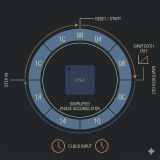
What is an NCO?
NCO stands for Numerically Controlled Oscillator.
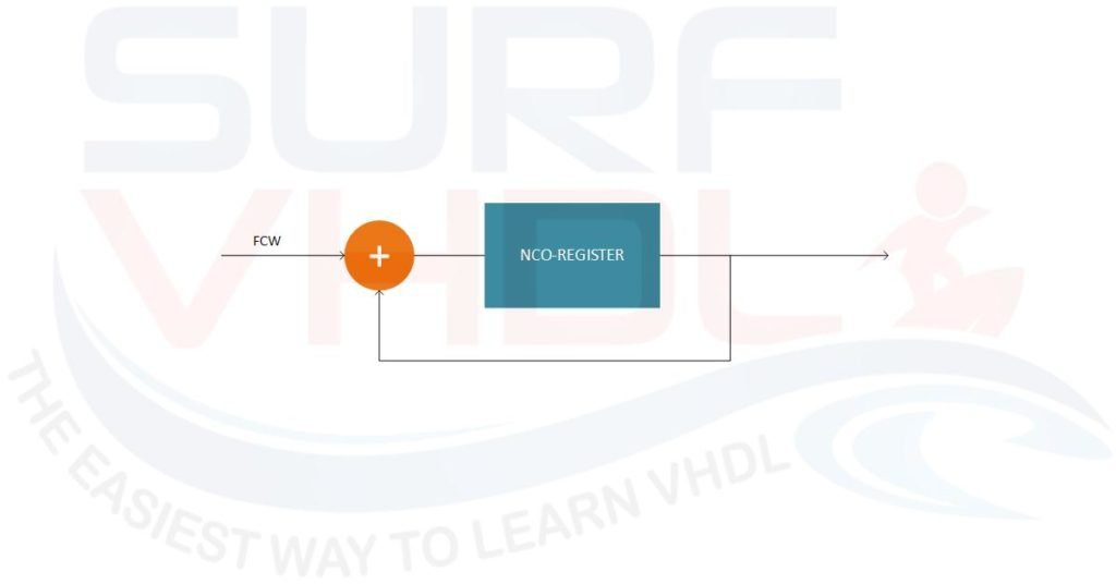
Figure 1 – NCO basic architecture
Basically, it is implemented with an accumulator which adds a constant value FCW (Frequency Control Word). The accumulator wraps around every time it reaches its maximum value. For example, if the maximum value is 15 (4-bit accumulator) and the FCW = 4, the accumulator will count:
0, 4, 8, 12, 1, 5, 9… and so on.
The NCO is widely used in digital signal processing. In this post, we are going to understand how to implement an NCO in VHDL.
You can also check the Wikipedia page on NCO for further info regarding the math behind the NCO. Here we want to focus on the VHDL implementation of the NCO.
NCO use in digital processing
The NCO is widely used in the digital implementation of DDS, digital UP/Down converter, Variable clock generation, digital PLL.
You can find an NCO inside a DAC such as DAC5687 Interpolated DAC
The DAC5687 is a dual-channel 16-bit high-speed digital-to-analog converter (DAC) with integrated 2×, 4×, and 8× interpolation filters, a complex numerically controlled oscillator (NCO), onboard clock multiplier, and Phase IQ compensation, and on-chip voltage reference. The DAC architecture is reported below. In this architecture, the NCO provides a frequency up-conversion of the input signal.
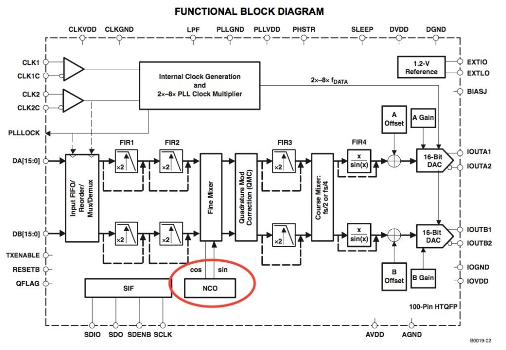
Figure 2 – DAC 5687 architecture
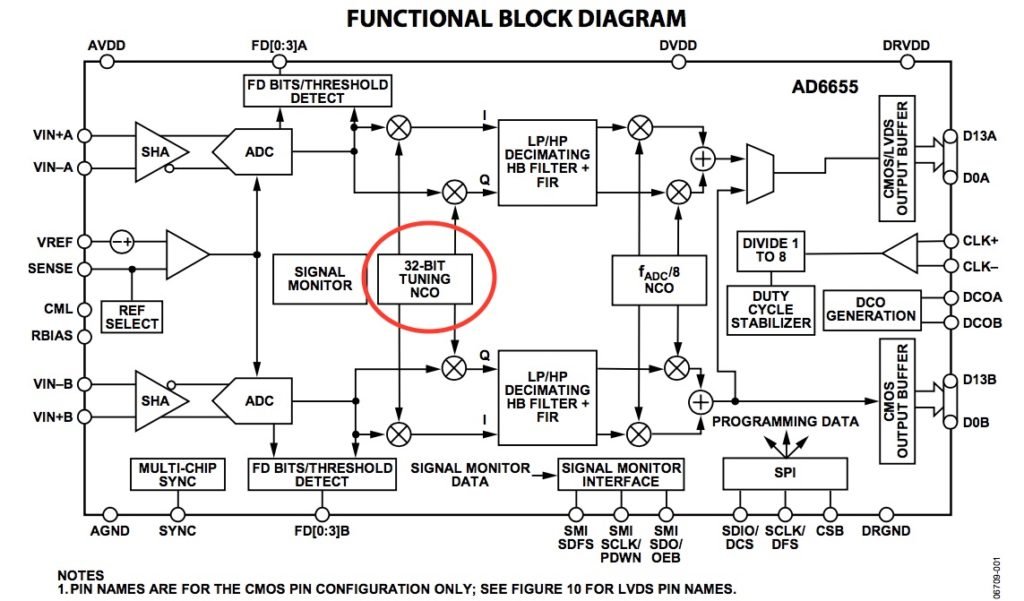
Another example is the Digital I/Q demodulator integrated into ADC AD6655. In this case, the NCO is used to implement a frequency down-conversion
NCOs are also widely used inside microcontrollers, for example to implement PWM as in Figure 4.
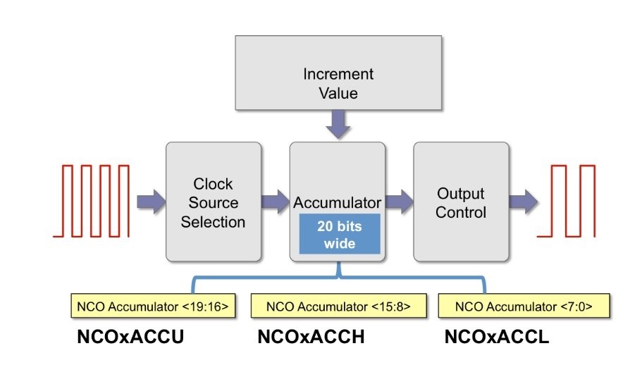
Figure 4 – PWM implementation using NCO in PIC microcontroller
We could continue with several other examples of NCO usage in digital but it is time to see how to implement an NCO in VHDL for our use.
NCO fixed-point implementation
To implement an NCO on FPGA or ASIC we need to quantize the NCO. Generally, the number of bits used in the NCO quantization is in the range of 24-48 bits.
For a 32-bit quantization, the frequency resolution of the NCO is Fc/2^32,
where Fc is the clock frequency of the system.
For example, if the clock frequency is 100 MHz the frequency resolution will be:
100.000.000/ 4.294.967.296 = 0,023 Hz
More generally, the wrap-around frequency Fw is given in (Eq.1)
Fw = Fc x FCW/(2^N) (Eq.1)
Where N = number of bits of the NCO
Example:
If N = 16, Fc = 100 MHz, Fw = 10 MHz

FCW = 10/100 x 65536 = 6553
In this case, with
FCW = 6553 the Fw = 100x6553/65536 = 9,9990844726562500 MHz
Or in the case of ceiling the result:
FCW = 6554 the Fw = 100x6554/65536 = 10,000610351562500 MHz
As you can see, in this case, since Eq.1 doesn’t give an integer result the final NCO frequency contains an error with respect to the desired frequency due to the rounding or truncation of the Frequency Control Word (FCW).
NCO VHDL implementation
In this section, we are going to understand how to implement an NCO in VHDL.
Before diving into the VHDL code, try the interactive simulation below. It lets you experiment with the Frequency Control Word (FCW) and start phase, and see in real time how the accumulator and output waveform behave.
NCO Interactive Simulation
How to Implement NCO in VHDL
Get the complete VHDL code from this article.
8-bit NCO basic implementation
Let’s start with a simple implementation of an 8-bit NCO.
library ieee;
use ieee.std_logic_1164.all;
use ieee.numeric_std.all;

entity nco8 is
port (
  i_clk                       : in  std_logic;
  i_rstb                      : in  std_logic;
  i_sync_reset                : in  std_logic;
  i_fcw                       : in  std_logic_vector(7 downto 0);
  o_nco                       : out std_logic_vector(7 downto 0));
end nco8;

architecture rtl of nco8 is
signal r_sync_reset                : std_logic;
signal r_fcw                       : unsigned(7 downto 0);
signal r_nco                       : unsigned(7 downto 0);

begin

p_nco8 : process(i_clk,i_rstb)
begin
  if(i_rstb='0') then
    r_sync_reset      <= '1';
    r_fcw             <= (others=>'0');
    r_nco             <= (others=>'0');
  elsif(rising_edge(i_clk)) then
    r_sync_reset      <= i_sync_reset   ;
    r_fcw             <= unsigned(i_fcw);
    if(r_sync_reset='1') then
      r_nco             <= (others=>'0');
    else
      r_nco             <= r_nco + r_fcw;
    end if;
  end if;
end process p_nco8;

o_nco            <= std_logic_vector(r_nco);

end rtl;
VHDL code of an NCO
The NCO VHDL code implements an accumulator that will accumulate the input FCW register when the synchronous “i_sync_reset” control signal value is zero.
As is clear from the VHDL code, the input signals are registered using an assignment under the clocked process to achieve better results in terms of static timing analysis, i.e. timing performance.
If you don’t want to add the input registers, you must ensure the input signal is already registered in the same clock domain of the NCO clock.
This is especially important for the “i_sync_reset” signal if you want to guarantee the functionality of the NCO.
Using an asynchronous signal, i.e. a signal from a different clock domain, is a classic error in VHDL design, even made by experienced designers.
NCO VHDL simulation
Figure 5 shows the simulation of the VHDL code of the NCO where the Frequency Control Word (FCW) is set to 19.
In this case, the 8-bit NCO wraps at 2^8 = 256. The wrapping period will be:
256/19 = 13.47 i.e. a non-integer number. As is clear from the figure, the wrapping cycle alternates between 13 and 14; in the long term, the average will be around 13.47. In the simulation, the clock cycle is set to 10 ns, so 140 ns corresponds to 14 clock cycles.
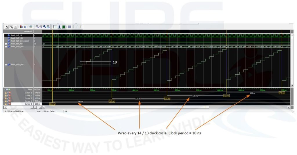
Figure 5 – 8-bit NCO simulation with FCW=19
NCO VHDL implementation with start phase
When using an NCO, you sometimes need to provide a start phase different from zero.
For example, when you use an NCO to drive a SIN/COS table or a CORDIC to implement a trigonometric function. An example of NCO with start phase architecture is given in Figure 6.
NCO with programmable start phase
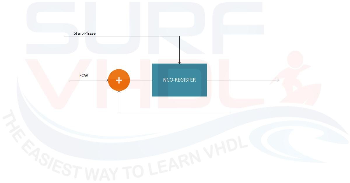
Figure 6 – NCO with Start-Phase control
In this case, the start-phase value will be loaded into the NCO accumulator register when the NCO is under synchronous reset.
The VHDL code for an NCO with start phase can be written as follows:
library ieee;
use ieee.std_logic_1164.all;
use ieee.numeric_std.all;

entity nco8_phase is
port (
  i_clk                       : in  std_logic;
  i_rstb                      : in  std_logic;
  i_sync_reset                : in  std_logic;
  i_start_phase               : in  std_logic_vector(7 downto 0);
  i_fcw                       : in  std_logic_vector(7 downto 0);
  o_nco                       : out std_logic_vector(7 downto 0));
end nco8_phase;

architecture rtl of nco8_phase is
signal r_sync_reset                : std_logic;
signal r_start_phase               : unsigned(7 downto 0);
signal r_fcw                       : unsigned(7 downto 0);
signal r_nco                       : unsigned(7 downto 0);

begin

p_nco8 : process(i_clk,i_rstb)
begin
  if(i_rstb='0') then
    r_sync_reset      <= '1';
    r_start_phase     <= (others=>'0');
    r_fcw             <= (others=>'0');
    r_nco             <= (others=>'0');
  elsif(rising_edge(i_clk)) then
    r_sync_reset      <= i_sync_reset   ;
    r_start_phase     <= unsigned(i_start_phase);
    r_fcw             <= unsigned(i_fcw);
    if(r_sync_reset='1') then
      r_nco             <= r_start_phase;
    else
      r_nco             <= r_nco + r_fcw;
    end if;
  end if;
end process p_nco8;

o_nco            <= std_logic_vector(r_nco);

end rtl;
NCO VHDL simulation with different start phase
Figure 8 shows the simulation of the VHDL code of the NCO with start phase. The test bench instantiates two identical 8-bit NCO with the same Frequency Control Word (FCW) and different start phase as in Figure 7
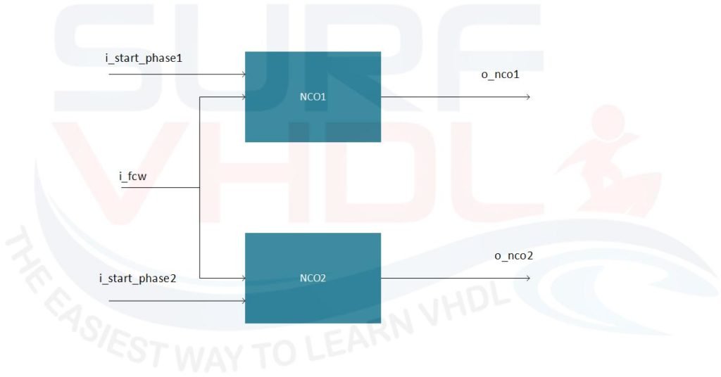
Figure 7 – NCO test bench with two NCO, different start phase same FCW
FCW is set to 19 as the previous example, start_phase=0; start_phase2=16. In this case, the 8-bit NCO wraps at 2^8 = 256 with a wrapping period of 256/19 = 13.47 i.e. a non-integer number. So the wrapping cycle alternates between 13 and 14. The two NCOs start at the same time and due to the different start phase, the wrapping instant differs between the two NCOs.
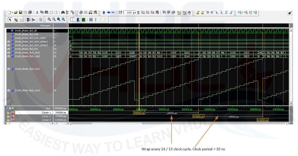
Figure 8 – simulation of two 8-bit NCO with different start phase 0, 16 and FCW=19
Conclusion
In this post we covered the basics of NCO design and implementation in VHDL, from the fixed-point math to the RTL code.
The NCO is a fundamental building block for DDS, digital up/down converters, and many other signal processing applications.
The VHDL examples provided can be used as a starting point for your own designs.
If you appreciated this post, please help us share it with your friends.
If you need to contact us, please write to: surf.vhdl@gmail.com