I wrote many posts on different VHDL topics. Many of them deal with quite a complex concept.
Some days ago, I realized that I didn’t write anything “simple” dealing with the basic hardware building block.
I realized that since I received many email and telegram messages asking me to explain them some line of VHDL code. These lines are relative to a simple shift register implementation.
Sometimes what is simple for you, is not for other people!
In this post, I would like to propose three different ways of implementing a shift register in VHDL.
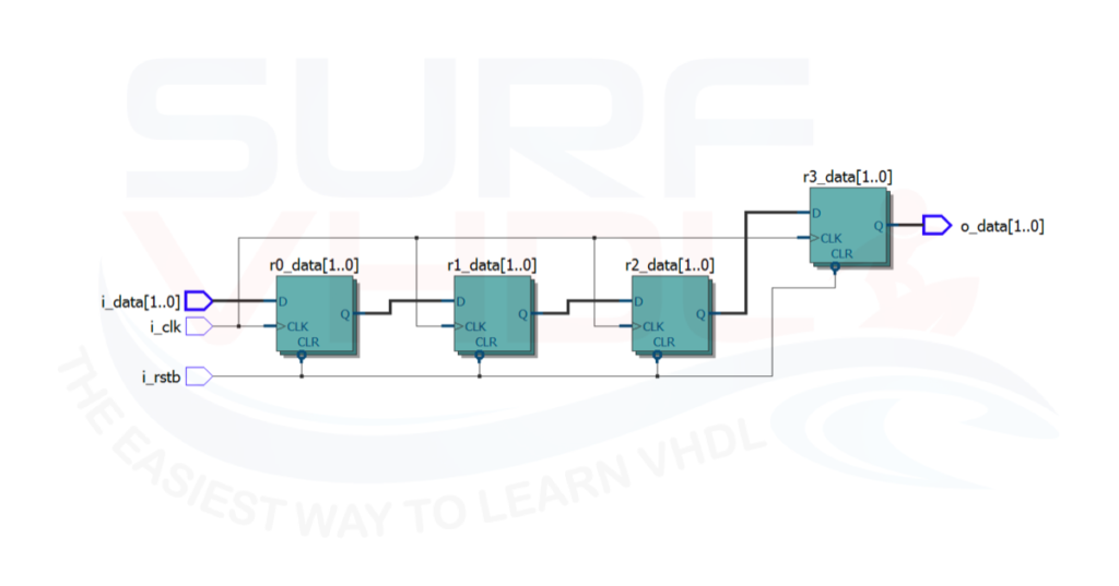
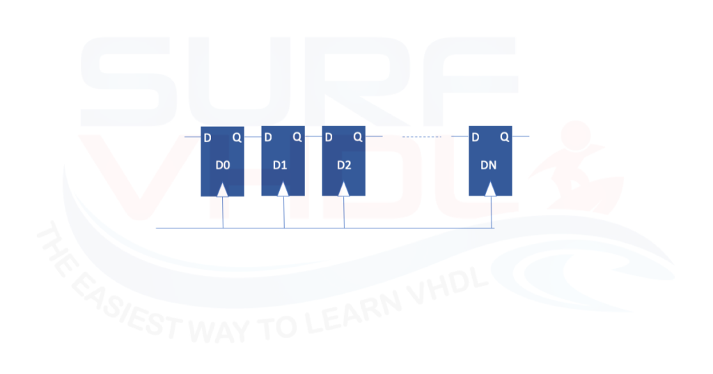
First of all, let’s review what is a shift register. It could be represented with a series of flip flop connected in series, where the output of one flip-flop is the input of the other.
In Figure 1 you can see a visual representation.
As stated before, there are at least three different ways to describe such hardware structure in VHDL. The three descriptions are totally equivalent.
Shift register VHDL plain description
A plain description of the shift registers in Figure 1 is reported in the VHDL code below.
library ieee;
use ieee.std_logic_1164.all;

entity shift_register is
port (
	i_clk          : in  std_logic;
	i_rstb         : in  std_logic;
	i_data         : in  std_logic_vector(1 downto 0);
	o_data         : out std_logic_vector(1 downto 0));
end shift_register;

architecture rtl of shift_register is
signal r0_data         : std_logic_vector(1 downto 0);
signal r1_data         : std_logic_vector(1 downto 0);
signal r2_data         : std_logic_vector(1 downto 0);
signal r3_data         : std_logic_vector(1 downto 0);

begin

o_data  <= r3_data;

p_sreg : process(i_clk,i_rstb)
begin
	if(i_rstb='0') then
		r0_data    <= (others=>'0');
		r1_data    <= (others=>'0');
		r2_data    <= (others=>'0');
		r3_data    <= (others=>'0');
	elsif(rising_edge(i_clk)) then
		r0_data    <= i_data;
		r1_data    <= r0_data ;
		r2_data    <= r1_data ;
		r3_data    <= r2_data ;
	end if;
end process p_sreg;
end rtl;
Shift register VHDL description #1
In this case, each register is declared in the architecture declarative part. For sure, this is a straight forward VHDL description for a shift register.
As you should know, since flip-flop are declared as a signal, you can modify the assignment order without changing the final result.
library ieee;
use ieee.std_logic_1164.all;

entity shift_register is
port (
	i_clk          : in  std_logic;
	i_rstb         : in  std_logic;
	i_data         : in  std_logic_vector(1 downto 0);
	o_data         : out std_logic_vector(1 downto 0));
end shift_register;

architecture rtl of shift_register is

begin


p_sreg : process(i_clk,i_rstb)
variable v0_data         : std_logic_vector(1 downto 0);
variable v1_data         : std_logic_vector(1 downto 0);
variable v2_data         : std_logic_vector(1 downto 0);
begin
	if(i_rstb='0') then
		v0_data    := (others=>'0');
		v1_data    := (others=>'0');
		v2_data    := (others=>'0');
		o_data     <= (others=>'0');
	elsif(rising_edge(i_clk)) then
		o_data     <= v2_data ;
		v2_data    := v1_data ;
		v1_data    := v0_data ;
		v0_data    := i_data;
	end if;
end process p_sreg;
end rtl;
Shift register VHDL description #2
In Figure 2 and Figure 3 are reported a layout example of Shift register VHDL description #1 and description#2.
The RTL view is totally equivalent, i.e. the two VHDL codes implement the same hardware.
- description #1 VHDL code for shift register implemented using signal
- description#2 VHDL code for shift register implemented using variable
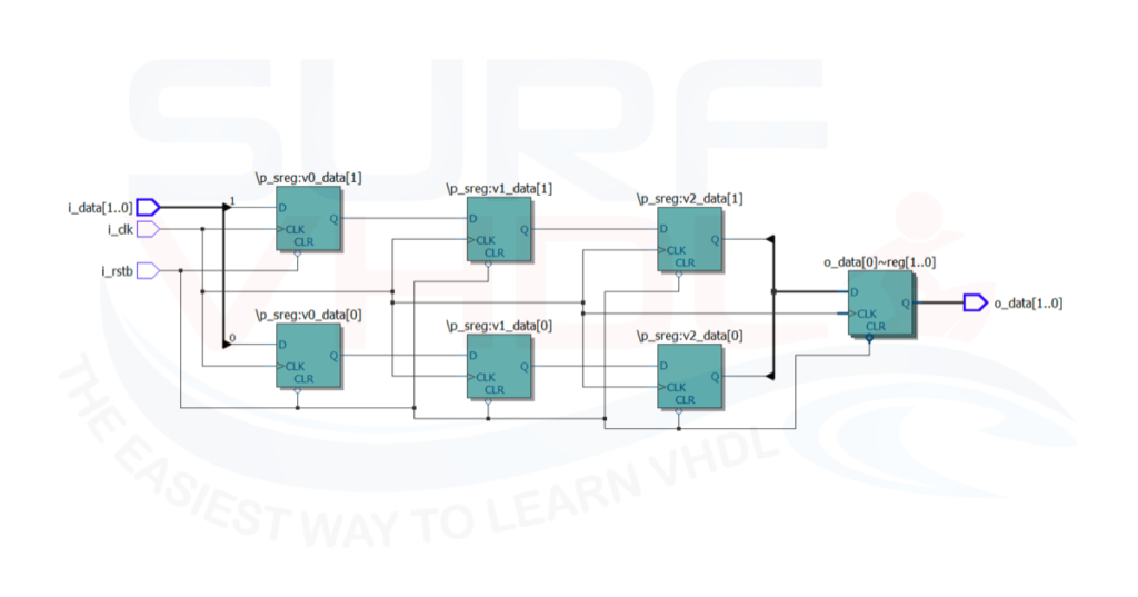
This approach is useful when you need different shift-register avoiding the declaration of a lot of signals.
As you know, the variables are local to the process where you declare them. So, you can use always the same process implementing a different set of shift-registers. It is a way to encapsulate the code, something like a component instantiation.
In the case of shift-register implemented using variables, you must pay attention to the assignment order. For the variable the value is assigned immediately, it is not scheduled and it is performed immediately.
Shift register VHDL for-loop description
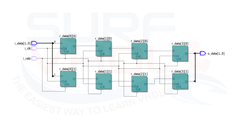
A more efficient VHDL shift register implementation, in terms of VHDL code description, can be achieved using for-loop iterative statement. With respect to the shift register plain description, the VHDL for-loop implementation can be parametrized.
In the VHDL code, we used a type declaration for the shift register so the number of shift registers to be implemented can be passed as constant or generic in the VHDL entity.
library ieee;
use ieee.std_logic_1164.all;

entity shift_register is
port (
	i_clk          : in  std_logic;
	i_rstb         : in  std_logic;
	i_data         : in  std_logic_vector(1 downto 0);
	o_data         : out std_logic_vector(1 downto 0));
end shift_register;

architecture rtl of shift_register is

type t_sreg is array(0 to 3) of std_logic_vector(1 downto 0);
signal r_data               : t_sreg;

begin

o_data     <= r_data(r_data'length-1) ;

p_sreg : process(i_clk,i_rstb)
begin
	if(i_rstb='0') then
		r_data    <= (others=>(others=>'0'));
	elsif(rising_edge(i_clk)) then
		r_data(0)    <= i_data;
		for idx in 1 to r_data'length-1 loop
			r_data(idx)    <= r_data(idx-1) ;
		end loop;
	end if;
end process p_sreg;
end rtl;
Shift register VHDL description #3
Even in this case, we can use a variable description for the shift register VHDL implementation.
Shift register single line VHDL description
The last shift-register implementation is my preferred one. It is a very compact VHDL code description. You can implement a shift-register in a parametric way with a single line of VHDL code. Cool!
library ieee;
use ieee.std_logic_1164.all;

entity shift_register is
port (
	i_clk          : in  std_logic;
	i_rstb         : in  std_logic;
	i_data         : in  std_logic_vector(1 downto 0);
	o_data         : out std_logic_vector(1 downto 0));
end shift_register;

architecture rtl of shift_register is

type t_sreg is array(0 to 3) of std_logic_vector(1 downto 0);
signal r_data               : t_sreg;

begin

o_data     <= r_data(r_data'length-1) ;

p_sreg : process(i_clk,i_rstb)
begin
	if(i_rstb='0') then
		r_data    <= (others=>(others=>'0'));
	elsif(rising_edge(i_clk)) then
		r_data    <= i_data&r_data(0 to r_data'length-2);
	end if;
end process p_sreg;
end rtl;
Shift register VHDL description #4
In this description, the shift functionality is implemented using the assignment feature provided by VHDL. The VHDL allow assigning object of the same type in a single line of code.
For instance, you cannot perform the same assignment in C.
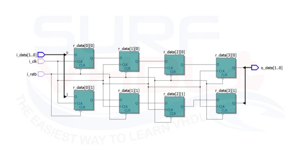
As you can see this shift-register description take full advantage of VHDL power description.
If you need to describe a very huge shift-register you can do it with a single VHDL line of code!
Of course, pay attention, you can fill an FPGA with a single VHDL line of code!
As clear from Figure5 the single line VHDL shift register implementation produce the same output of the other two shift register description.
Conclusion
In this post, we clarified how to implement a shift-register in VHDL using three different approaches. The first approach is very clear and straight forward. As a drawback, it is not parametrizable.
The second approach uses the for-loop VHDL statement. It is simple to read and understand, and it is parametrizable.
The third approach takes advantage of the power of VHDL syntax. In this case, we can describe a shift register with a single VHDL line code. It is less intuitive but very elegant and compact.
The VHDL code relative to the shift register implementation above has been layout using Intel Quartus II v 13 web edition
I hope you find this post useful, and if you have any question or you want to propose another shift-register VHDL implementation, just comment below.
I hope you find this post useful, and if you have any question or you want to propose another shift-register VHDL implementation, just comment below.
“Sometimes what is simple for you, is not for other people!” This is especially true for someone who just started learning FPGA and VHDL like myself.
The last implementation is probably the most difficult to understand, but it is very compact. I think it is also used in FIR filter example. When I first saw that line of code, it took me a lot of time to understand.
Thank for this great blog post!
Thank you for your great feedback!