The real mixing refers to the translation of a signal in frequency by multiplying it with a single oscillator signal as in figure below
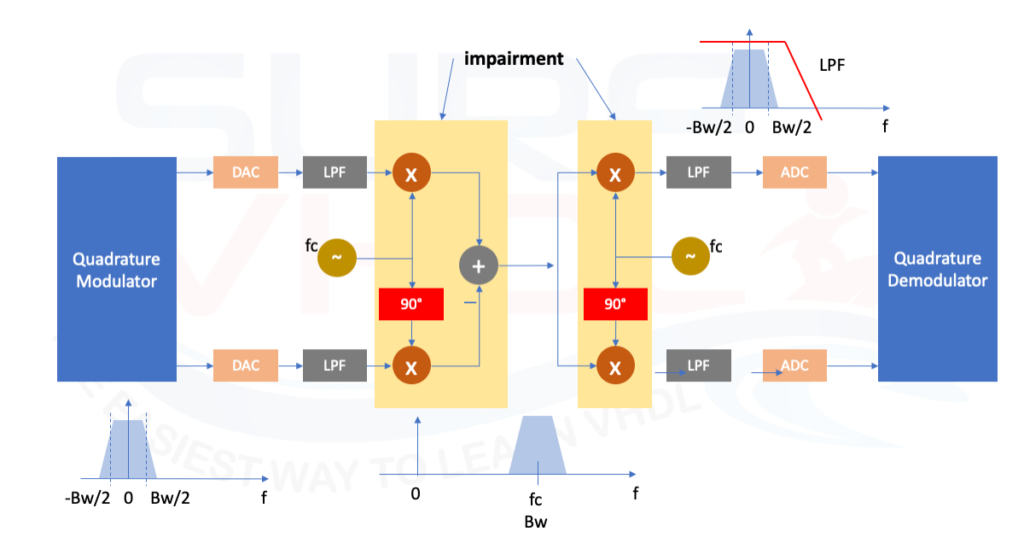
This approach is performed using the I/Q modulator technique. The I/Q modulator is a critical component in the signal chain for modern digital transmitters. An I/Q modulators perform the frequency translation that mixes the baseband signal to the desired location in the RF spectrum. An I/Q modulator consists of a local oscillator (LO) input that is split into in-phase (I) and quadrature (Q) components that are separated by 90°. An example of I/Q modulator is given in [3] These two signals drive separate mixers that are also driven by I and Q baseband signals processor.
This approach creates a complex baseband signal that occupies only a single sideband in the range [0,Bw] Hz or one that carries unique information in the frequencies [−Bw,0) Hz and [0,Bw] Hz. By using complex signal processing, it is possible to perform a true single frequency translation, with theoretically infinite image frequency rejection.
Imbalance Quadrature Modulation and Demodulation
The quadrature modulator and demodulator can theoretically provide infinite image signal suppression without the need for expensive, extra hardware or multiple mixing and filtering stages. This is true only for ideal quadrature modulators and demodulators.
The image-rejection capabilities of the quadrature mixing architecture degradates in the presence of so-called quadrature imbalances
- I/Q gain imbalance: the gains of the I and Q channels are not perfectly matched
- I/Q phase imbalance: the I and Q signals phase difference is not exactly 90°.
Imbalance Quadrature Modulation Pre-compensation
In the I/Q modulation scheme of Figure1, the I/Q imbalances produce an undesired alias signal reducing its signal-to-noise-and-distortion (SINAD) ratio. It can be demonstrated (see [3]) that when an imbalanced quadrature modulator is used,
The imbalanced quadrature modulator therefore causes leakage of the original I and Q channels into the real and imaginary part of the output baseband-equivalent signal. This “leakage” establishes a correlation in terms of the original real and imaginary components of the baseband transmit signal.

From Figure 2 the distorted signal uS(t) can be represented as a matrix product as follow:
uS(t) = A S(t)
Imbalance Quadrature Modulation Pre-compensation VHDL implementation
The VHDL code for I/Q modulator pre-compensation is directly derived from EQ.1. and Figure 2
If we take as reference the channel I the matrix coefficient can be simplifies as in EQ.1:

gI can be assumed as =1 since is only an additional gain.
Where

The VHDL implementation of an I/Q modulator phase and amplitude pre-compensator is straight forward in EQ.2:

As clear we need to work in fixed point arithmetic, so we need to quantize the coefficient a12 and a21. The number of bit used for the quantization is directly proportional to the I/Q imbalance error we can pre-compensate.
Assuming aQ = 0° the gain compensation can be assumed in the range
(1-1/2N) .. 1/2N where N is the number of bits we are using for gain quantization.
Assuming gM=1 the phase pre-compensation can be assumed in the range
0 .. (aQ /2pi) 2M where M is the number of bits we are using for phase quantization.
The number of bits for gain and phase pre-compensation will be M+N.
For the gain compensation we need to establish if we need only attenuation, only amplification or both. For instance, if we want to give an amplification by 3 and an attenuation by 7 we need to use 2.3 fixed point representation:
2^2 = 4 >3
2^(-3) = 1/8 < 1/7
If both gain and phase are different from 1 and zero the accuracy is a mix of the two formulas above.
The VHDL code for I/Q imbalance pre-compensator is given below:
library ieee;
use ieee.std_logic_1164.all;
use ieee.numeric_std.all;

entity iq_imbalance is
port (
	i_clk           : in  std_logic;
	i_rstb          : in  std_logic;
	-- coefficient
	i_a12           : in  std_logic_vector( 9 downto 0); -- 2.8
	i_a22           : in  std_logic_vector( 9 downto 0);
	-- data input
	i_data_re       : in  std_logic_vector(11 downto 0);
	i_data_im       : in  std_logic_vector(11 downto 0);
	-- filtered data
	o_data_re       : out std_logic_vector(11 downto 0);
	o_data_im       : out std_logic_vector(11 downto 0));
end iq_imbalance;

architecture rtl of iq_imbalance is

signal r_a12           : signed( 9 downto 0);
signal r_a22           : signed( 9 downto 0);
signal r_m12           : signed( 9+12 downto 0);
signal r_m22           : signed( 9+12 downto 0);
signal r_data_re       : signed( 9+12 downto 0);
signal r_data_re_c     : signed( 9+12 downto 0);
signal r_data_im_c     : signed( 9+12 downto 0);

begin

o_data_re    <= std_logic_vector(r_data_re_c( 9+12-2 downto 8));
o_data_im    <= std_logic_vector(r_data_im_c( 9+12-2 downto 8));

p_input : process (i_rstb,i_clk)
begin
	if(i_rstb='0') then
		r_a12           <= (others=>'0');
		r_a22           <= (others=>'0');
		r_m12           <= (others=>'0');
		r_m22           <= (others=>'0');
		r_data_re       <= (others=>'0');

		r_data_re_c     <= (others=>'0');
		r_data_im_c     <= (others=>'0');
	elsif(rising_edge(i_clk)) then
		r_a12           <= signed(i_a12);
		r_a22           <= signed(i_a22);
		r_m12           <= (signed(i_data_im) * r_a12);
		r_m22           <= (signed(i_data_im) * r_a22);
		r_data_re       <= shift_left(resize(signed(i_data_re),9+12+1),8);
		r_data_re_c     <= r_data_re + r_m12;
		r_data_im_c     <=             r_m22;
	end if;
end process p_input;

end rtl;
Imbalance Quadrature Modulation Pre-compensation VHDL Simulation
In the simulation the input I and Q are generated using the Matlab/Octave code given below.
The I/Q complex signal is generated with an I/Q gain imbalance of 5 dB and a phase imbalance of 4 degree.

Using these values, the pre-compensation values are:
a12 = 32
a22 = 452
The VHDL code above doesn’t check the output dynamic. The code wraps around if the output value is great than 12 bits.
In the simulation the input is selected such that the output dynamic is in the range of 12 bits. A possible solution to guarantee that no wrap-around occurs is to saturate the output.
As general rule, saturation is better than wrap-around:
- A wrap-around change the sign of the signal
- A saturation distorts the signal. When the saturation of small (few percentages of the entire dynamic) the distortion is negligible.
The MATLAB code used to generate the input distorted samples of IQ modulator for VHDL simulation is reported below:
Qdata = 2^11-30;  % to avoid saturation
Qcoeff = 2^8-1;

gydB = -5
gy=10^(gydB/20)
ay=4/180*pi;

% generate time base
f = 10;
npoint=1000;
t=linspace(0,1-1/npoint,npoint);

% generation of I/Q signal; Q imbalances
x=cos(2*pi*f*t);
y=gy*sin(2*pi*f*t+ay);

Conclusion
In this post, we learn how to pre-compensate the I/Q imbalance in TX for a quadrature modulator. In the post you find the VHDL implementation of the Amplitude and Phase imbalance for a quadrature modulator.
In the post MATLAB code used to compute equation can be used also in Octave totally compatible with MATLAB.
I read your code about iq-demodulation. I work in my thesis about signal processing with FPGA . Can you send me your test bench because i can’t insert float numbers in my test bench ? thank you for your time.