What is an RS-Encoder
When you want to transfer information from a source to a target, you want to be sure that such information is transferred without errors.
When you transfer an information through a communication channel, such information will be prone to errors.
In order to minimize or eliminate the number of errors during the information transmission, we can adopt some error correction strategies.

Such strategies are named FEC, i.e. Forward Error Correction. As you can imagine, nothing is for free. If you want to guarantee an error-free transmission you need to “pay” in terms of transmission bandwidth and transmitter/receiver complexity.
Any error correction strategy needs to transmit much more information than the minimum required, in order to allow the receiver to recognize if the received information is correct and, in case of error, provide to correct the errors.
Without entering in the error correction field theory, very complex and wide argument, here we want to address one possible error correction algorithm.
There are two main approaches to implement Error- Correction Coding:
- Block Coding: the symbol stream is divided into a block and coded.
- Convolution Coding: convolution operation is applied to the symbol stream.
In this post, we are going to introduce a widely used FEC algorithm. It is widely used in all our home electronics such as DVD, CD-ROM, TV decoder.
The algorithm is the Reed-Solomon a Block Coding algorithm, very simple to implement. We will address the VHDL implementation of an RS-Encoder that you can use as a template for your RS-encoder implementation.
We will verify the VHDL RS-Encoder implementation generating a coded reference data using Matlab or Octave.
In the post, you can find some Matlab/Octave commands that allow you to generate an RS coded stream for your design.
Introduction to Reed-Solomon encoder
There is a lot of documentation that can help you with the coding theory. You can find some references at the end of this post in the Reference section.
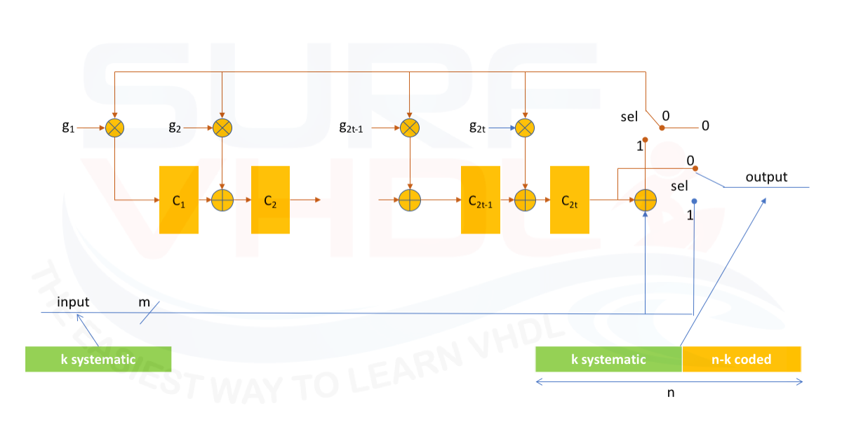
Here we want to address the hardware architecture of a Reed-Solomon encoder. It can be demonstrated that we can implement a Reed-Solomon encoder using the architecture of Figure 2

where
g(x) = (x+a^1)(x+a^2)...(x+a^2t)

m = number of bit

t = number of the errors that can be corrected by the algorithm

n =number of symbols of the RS coded message

k = number of systematic symbols (input information symbols)

n-k = 2t = number of coded symbols
Since the Reed-Solomon is a Block Coding algorithm is clear from Figure 2 that during the coded symbols computation the algorithm pass through the input to the output (sel=1).
After the systematic data section is entered in the RS-Encoder, the switch will be connected (sel=0) to the coded block section and all the coded symbols will be transmitted.
We need to remember that the Reed-Solomon algorithm belongs to the Galois Field arithmetic, so the sum and multiplication operations are different from the normal 2’complements operation.
The SUM is implemented as bitwise XOR.
The multiplication operation is a little bit more complicated. In this post, you can find a VHDL implementation of a multiplier in the Galois Field.
Now that we have clear how to implement the ADD and MULT operation let’s go and try to implement a VHDL code for RS-Encoder.
VHDL code for Reed-Solomon Encoder
Here below we will implement the VHDL code for Reed-Solomon Encoder RS(7,3). This VHDL code can be easily modified to implement a differently encoded output.
If you want to go deeper into the multiplier function, you can read this post,
The RS(7,3) encoder will get 3 input symbols (k=3) and outputs 7 symbols (n=7) ;
n-k=2t=4
g(x) = (x+a)(x+a^2)(x+a^3)(x+a^4)
p(x) = x^3+x+1
m=3;
n=2^m - 1 =7
A possible VHDL implementation is:
library ieee;
use ieee.std_logic_1164.all;
use ieee.std_logic_arith.all;
use ieee.std_logic_unsigned.all;

entity rs_encoder_7_3 is
port (
  i_clk          : in  std_logic;
  i_rstb         : in  std_logic;
  i_start_enc    : in  std_logic;
  i_data_ena     : in  std_logic;
  i_data         : in  std_logic_vector(2 downto 0);
  o_encoding     : out std_logic;
  o_data_valid   : out std_logic;
  o_data         : out std_logic_vector(2 downto 0));
end rs_encoder_7_3;

architecture rtl of rs_encoder_7_3 is
constant C_N            : integer := 7;
constant C_K            : integer := 3;
constant C_M            : integer := 3;
constant C_T            : integer := C_N-C_K;

---------------------------------------------------------------------------------------------------
function  rise(val : in std_logic;  val_d : in std_logic ) return std_logic is
variable ret   : std_logic;
begin
  ret := not val_d and val;
  return ret;
end rise;
---------------------------------------------------------------------------------------------------
function mult13 (v1, v2 : in std_logic_vector) return std_logic_vector is
constant m              : integer := C_M;
variable dummy          : std_logic;
variable v_temp         : std_logic_vector(m-1 downto 0);
variable ret            : std_logic_vector(m-1 downto 0);

begin
  v_temp := (others=>'0');   -- D^3+D^2+1
  for i in 0 to m-1 loop
    dummy      := v_temp(2);
    v_temp(2 ) := v_temp(1 ) xor dummy;
    v_temp(1 ) := v_temp(0 );
    v_temp(0 ) := dummy;

    for j in 0 to m-1 loop
      v_temp(j) := v_temp(j) xor (v1(j) and v2(m-i-1));
    end loop;
  end loop;
  ret := v_temp;
  return ret;
end mult13;
----------------------------------------------------------------------------------------------------
type t_pipe_enc is array (1 to C_T) of std_logic_vector(C_M-1 downto 0);

constant G_GPOLY        : t_pipe_enc := (
   conv_std_logic_vector(5,C_M),
   conv_std_logic_vector(1,C_M),
   conv_std_logic_vector(5,C_M),
   conv_std_logic_vector(4,C_M));

type t_pipe_data is array (0 to 2) of std_logic_vector(C_M-1 downto 0);

signal p_start_enc                       : std_logic_vector(0 to 2);
signal p_data_ena                        : std_logic_vector(0 to 2);
signal p_data                            : t_pipe_data;
signal r_pipe_enc                        : t_pipe_enc;
signal w_pipe_enc                        : t_pipe_enc;
signal w_feedback                        : std_logic_vector(C_M-1 downto 0);
signal w_start_enc                       : std_logic;
signal w_sel                             : std_logic;
signal w_ecoder_enable                   : std_logic;
signal r_counter                         : integer range 0 to C_N;
signal w_counter_tc                      : std_logic;
signal r_encoding                        : std_logic;

begin

w_feedback     <= p_data(2) xor r_pipe_enc(C_T) when(w_sel='1') else (others=>'0');

g_pipe_enc :  for i in 1 to C_T generate
  w_pipe_enc(i)  <= mult13(G_GPOLY(i),w_feedback);
end generate;

p_enc : process(i_clk,i_rstb)
begin
  if(i_rstb='0') then
    r_pipe_enc     <= (others=>(others=>'0'));
    o_data         <= (others=>'0');
    o_data_valid   <= '0';
  elsif(rising_edge(i_clk)) then
    o_data_valid   <= w_ecoder_enable;
    if(w_ecoder_enable='1') then
      for i in 2 to C_T loop
        r_pipe_enc(i)     <= r_pipe_enc(i-1) xor w_pipe_enc(i);
      end loop;
      r_pipe_enc(1)     <= w_pipe_enc(1);

      if(w_sel='1') then
        o_data         <= p_data(2);
      else
        o_data         <= r_pipe_enc(C_T);
      end if;
    end if;
  end if;
end process p_enc;

w_start_enc       <= rise(p_start_enc(0),p_start_enc(1));
w_counter_tc      <= '0' when (r_counter<C_N) else '1';
w_sel             <= '1' when (r_counter<C_K) else '0';
w_ecoder_enable   <= p_data_ena(2) when (w_sel='1') else
                     '1'           when (w_counter_tc='0') else '0';

o_encoding        <= r_encoding;
p_enc_control : process(i_clk,i_rstb)
begin
  if(i_rstb='0') then
    r_encoding      <= '0';
    r_counter       <= C_N;
    p_start_enc     <= (others=>'0');
    p_data_ena      <= (others=>'0');
    p_data          <= (others=>(others=>'0'));
  elsif(rising_edge(i_clk)) then
    p_start_enc     <= i_start_enc &p_start_enc(0 to p_start_enc'length-2);
    p_data_ena      <= i_data_ena  &p_data_ena (0 to p_data_ena 'length-2);
    p_data          <= i_data      &p_data     (0 to p_data     'length-2);
    if(w_start_enc='1') then
      r_encoding      <= '1';
    elsif(w_counter_tc='1') then
      r_encoding      <= '0';
    end if;

    if(w_start_enc='1') then
      r_counter       <= 0;
    elsif(w_sel='1' and p_data_ena(2)='1') then
      r_counter       <= r_counter + 1;
    elsif(w_sel='0' and w_counter_tc='0') then
      r_counter       <= r_counter + 1;
    end if;
 	end if;
end process p_enc_control;

end rtl;
In the VHDL code, the control logic for sel signal is implemented using a counter.
The counter computes the number of input symbols. When the input symbols are equal to k the control logic set the signal sel=0 and flush the coding registers to the output.
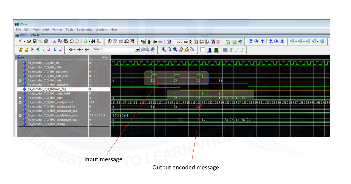
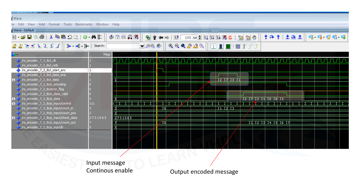
The simulation of Figure3 and 4 should clarify the behavior. The VHDL code for the Reed-Solomon encoder can be easily modified using the constant in the architecture declaration section. If you need to change the primitive polynomial and the generation polynomial you need to update the constant G_POLY and the multiplier function accordingly.
In order to generate the polynomial g(x) you can use the following Matlab/Octave code:
% ONLY for Octave
pkg load communications


prim_poly = 13;
m = 3;           % Number of bits per symbol
n = 2^m - 1;     % Codeword length
k = 3;           % Message length

% message to be codede
x = [2 7 3; 4 0 6; 5 1 7]

genpoly = rsgenpoly(n,k,prim_poly) % Use nondefault primitive polynomial.

g = genpoly((n-k)+1:-1:2)'

% Create two messages based on GF(8).

msg = gf(x,m,prim_poly)

% Generate RS (n,k) codewords.

code = rsenc(msg,n,k,genpoly)
If you need to generate the encoded message using Matlab/Octave here below there is the example used to generate the reference message of the simulation in
If you are using Octave, you need to add the first line to load the communication package.
VHDL code Simulation for Reed-Solomon Encoder
In the figures below is reported the Modelsim simulation of the VHDL code above using the message generated by the above Matlab script.


The yellow signal is introduced to help the matching process with Matlab reference encoded message.
VHDL code Layout for Reed-Solomon Encoder
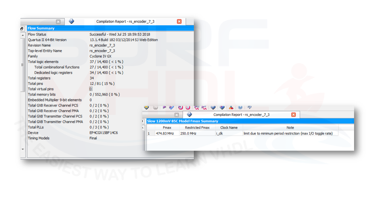
In FIGURE is reported an example of a layout on Cyclone IV Altera/Intel FPGA. As clear from the report in Figure 5 the Reed-Solomon encoder RS(7,3) takes only 37 logic element and 34 registers. The timing analysis reports a 474 MHz as the clock frequency.

Conclusion
In this post, we addressed the realization of a VHDL code for a Reed-Solomon encoder. In the post, you can find the Matlab or Octave code to generate the generator polynomial and a reference encoded message for your Reed-Solomon encoder. You can use the Matlab code as a reference for your VHDL implementation.
References
[2] https://www.mathworks.com/
[4] https://www.gnu.org/software/octave/
[5] https://en.wikipedia.org/wiki/Finite_field
[9] “Reed-Solomon error correction, R&D White Paper WHP 031”, C.K.P. Clarke
[11] “Reed Solomon Codes Explained” Tony Hill, 8th May 2013, v1-0
[12] “VHDL Implementation of Reed Solomon Improved Encoding Algorithm”
[13] “VHDL IMPLEMENTATION OF REED-SOLOMON CODING”, SUBHASHREE DAS
[16] “Galois Field in Cryptography”, Christoforus Juan Benvenuto
[17] APPLICATIONS OF REED-SOLOMON CODES ON OPTICAL MEDIA STORAGE
[18] https://en.wikipedia.org/wiki/Forward_error_correction
[19] APPLICATIONS OF REED-SOLOMON CODES ON OPTICAL MEDIA STORAGE
Great article! Is it possible to post the Testbenches as well? Thank you in advance
So helpful !!
I’d like to ask you how did you choose the G_poly :
constant G_GPOLY : t_pipe_enc := (
conv_std_logic_vector(5,C_M),
conv_std_logic_vector(1,C_M),
conv_std_logic_vector(5,C_M),
conv_std_logic_vector(4,C_M)); Please??
I can’t understand the structure of this conversion nor the values “5,1,5,4” that you picked to generate this poly
is simply a constant array
(5,1,5,4)
represented as std_logic_vector at C_M bits
But what is the logic behind using 5,1,5,4 to create this constant array?
it is the generator polynomial for RS(7,3)
https://it.mathworks.com/help/comm/ref/rsgenpoly.html
In VHDL code you use the polynomial p(x) = x^3+x^2+1. But in the parameters before the code you declare that the code polynomial is p(x) = x^3+x+1.