Binary Counters vs BCD Counters
A counter is a common component in VHDL design. When we deal with FPGA, the most used counters are the binary counter.
These counters use the modulo-two arithmetic.
For example, of a 3-bit counter, the values that can be addressed are
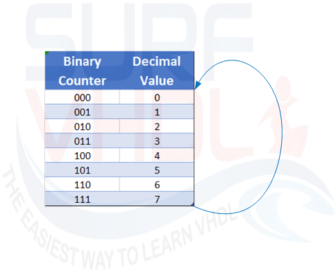
then the counter wrap-around starting again from zero, as clear in Figure 1.
In dealing with the digital design we use base 2 arithmetic because all the logic and arithmetic is optimized for 2’complement representation.
Here you can find an example of binary number representation.
In our daily life, we use to process our math operation in base 10. A base 10 counter wrap-around when reach value 9.
There is the possibility to emulate a base 10 using a binary counter. Such type of counters is named BCD counter.
BCD state for Binary Coded Decimal counter. Of course, a BCD counter is not optimized for base 2 arithmetic.
In hardware implementation such as FPGA or ASIC, this kind of counters requests an additional logic gate to be implemented.
Why should we need a BCD counter?
There are some applications that can take advantage of BCD counter.
Taking aside the homework that can be assigned to a future young engineer, a possible application could be the implementation of a counter that displays the count result on a 7-segment display, without the need of binary-to-decimal conversion before the display.
In the past, the computer BIOS were implemented using BCD representation, ATARI consoles used BCD as well.
Implementing a BCD counter in VHDL
A BCD counter can be easily implemented with a 4-bit binary counter as in the Figure2 below
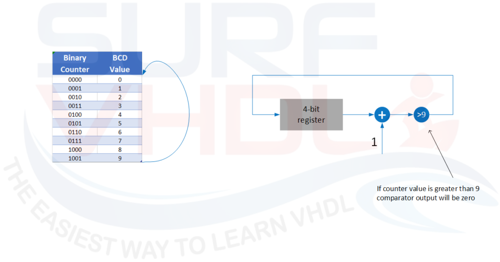
The BCD counter architecture can be represented using an unsigned binary accumulator that increment by 1, and a comparator.
When the counter reaches 9, next count value will be 0, then the 4-bit counter wraps at 9 (“1001”), not at 15 (“1111”) as a 4-bin binary counter does.
A possible VHDL code of a BCD implementation is reported below:
library ieee;
use ieee.std_logic_1164.all;
use ieee.numeric_std.all;

entity bcd_counter1 is
port (
  i_clk                       : in  std_logic;
  i_rstb                      : in  std_logic;
  i_sync_reset                : in  std_logic;
  i_count_ena                 : in  std_logic;
  o_bcd                       : out std_logic_vector(3 downto 0));
end bcd_counter1;

architecture rtl of bcd_counter1 is
signal r_count                 : unsigned(3 downto 0);

begin

o_bcd  <= std_logic_vector(r_count);
p_count : process(i_clk,i_rstb)
begin
  if(i_rstb='0') then
    r_count      <= (others=> '0');
  elsif(rising_edge(i_clk)) then
    if(i_sync_reset='1') then
      r_count      <= (others=> '0');
    elsif(i_count_ena='1') then
      if(r_count = 9) then
        r_count      <= (others=> '0');
      else
        r_count      <= r_count + 1;
      end if;
    end if;
  end if;
end process p_count;

end rtl;
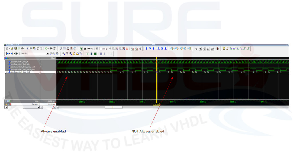
Figure3 is reported the simulation of the BCD counter
Four-digit BCD Counter
If we need to implement two or more digit BCD counter we need to handle the carry bit.
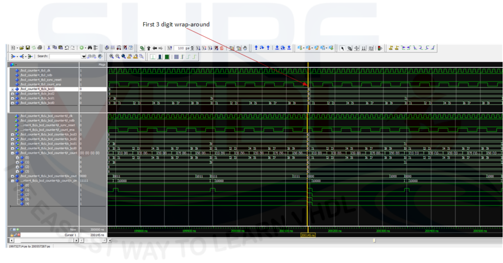
The carry is generated when the BCD counter reaches the value 9 and need to count more. An example of four-digit BCD counter architecture is reported in Figure4.
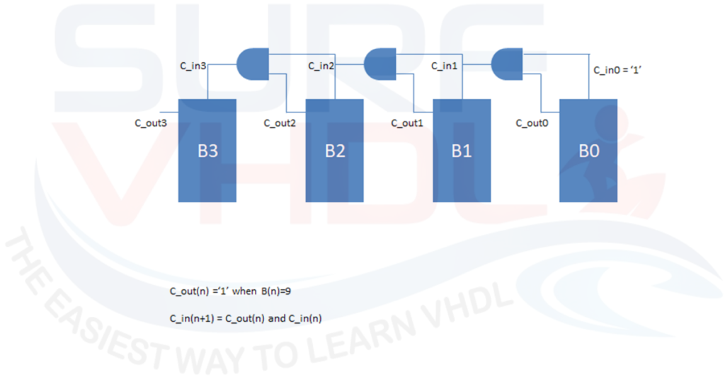
Figure5 shows the VHDL simulation of a four-digit BCD counter
If you want to receive the VHDL code of a 4-digit BCD counter with the complete VHDL test bench just put your email just below.
Conclusion
In this post, we implemented a BCD counter in VHDL.
One digit and 4-digit BCD counter architecture have been presented.
VHDL code for BCD counter can be copied and used in your VHDL design.
References
[1] https://en.wikipedia.org/wiki/Binary-coded_decimal
[2] https://en.wikipedia.org/wiki/Two%27s_complement
If you appreciated this post, please help us to share it with your friend.
[social_sharing style=”style-7″ fb_like_url=”https://surf-vhdl.com/how-to-implement-a-bcd-counter-in-vhdl” fb_color=”light” fb_lang=”en_US” fb_text=”like” fb_button_text=”Share” tw_lang=”en” tw_url=”https://surf-vhdl.com/how-to-implement-a-bcd-counter-in-vhdl” tw_button_text=”Share” g_url=”https://surf-vhdl.com/how-to-implement-a-bcd-counter-in-vhdl” g_lang=”en-GB” g_button_text=”Share” linkedin_url=”https://surf-vhdl.com/how-to-implement-a-bcd-counter-in-vhdl” linkedin_lang=”en_US” alignment=”center”]
If you need to contact us, please write to: surf.vhdl@gmail.com
We appreciate any of your comment, please post below:
Hello,
your implementation has some drawbacks and mistakes:
1. No target device (nor FPGA neither common ASIC libraries) support asynchronous and synchronous resets at the same time. You should decide for one.
2. You should prefer synchronous resets over asynchronous resets even in ASIC designs, unless you realy know what you are doing.
3. You naming scheme is inconsistent, because you synchronous reset containts “sync” in the name, while other synchronous signals are without “sync”. Moreover an asynchronous signal (‘i_rstb’) doesn’t reflect that behavior.
4. You intermix high- and low-active logic in the same circuit. You should always prefer high-active logic.
5. Fig. 4 refers to carry out (‘cout’) signals, whereas your listing doesn’t implement these signals. The same is true for carry in (‘cin’).
6. The displayed “carry chain” in Fig. 4 is not correct. The carry chain goes through your counters — if the would implement carry signals –, but not along the counters.
Hi Patrick,
thank you for your feedback.
It is possible to use both Sync and Async reset in FPGA and ASIC.
Generally, the asynchronous reset is active low, the other synchronous logic can be either active high or low. Some FPGAs have a recommendation about the usage but it is technology dependent.
Figure 4 is relative to the architecture of four-digit BCD counter. The VHDL code is not present in the post.
If you want to receive the VHDL code just sign in in the box appearing on the bottom left
Cheers!
code VHDL d’un compteur BCD à 4 chiffres
you can get the code, just put your email in the box above
cheers!
Agreed to all, Patrick Lehmann.
I edited the above code for Xilinx which uses synchronous, pos resets and moved the i_strb under the reset so that it acts like a reset independent of the sys reset giving the sys reset priority with both being synchronous and positive.
I also always initialize any inferred flops, shift regs and rams in the code. They are initialized before the sys reset this way and you can build in any inversions to the pre reset startup state of these inferred primitives which is sometimes real useful if supported and won’t hurt if it’s not.
I do this with enables too. Probably not necessary, but it can’t hurt to initialize any enable to their disabled default.
———————————————————————————-
— Company:
— Engineer:
—
— Create Date: 12/04/2017 03:15:59 PM
— Design Name:
— Module Name: BCD_cntr – Behavioral
— Project Name:
— Target Devices:
— Tool Versions:
— Description:
—
— Dependencies:
—
— Revision:
— Revision 0.01 – File Created
— Additional Comments:
—
———————————————————————————-
library ieee;
use ieee.std_logic_1164.all;
use ieee.numeric_std.all;
entity bcd_counter1 is
port (
i_clk : in std_logic;
i_rstb : in std_logic;
i_sync_reset : in std_logic;
i_count_ena : in std_logic;
o_bcd : out std_logic_vector(3 downto 0));
end bcd_counter1;
architecture rtl of bcd_counter1 is
signal r_count : unsigned(3 downto 0) := (others=> ‘0’);
signal i_count_ena_i : std_logic := ‘0’;
begin
o_bcd <= std_logic_vector(r_count);
i_count_ena_i <= i_count_ena;
p_count : process(i_clk)
begin
if(rising_edge(i_clk)) then
if(i_sync_reset = '1') then
r_count ‘0’);
elsif (i_rstb = ‘1’) then
r_count ‘0’);
elsif (i_count_ena_i = ‘1’) then
if(r_count = 9) then
r_count ‘0’);
else
r_count <= r_count + 1;
end if;
end if;
end if;
end process p_count;
end rtl;
You are initializing the signal ” r_count”. Asynchronous reset is different from initialization.
The initialization cannot be used, for example, in ASIC technology, so this code is not portable.
Initialization is valid only after the FPGA configuration
Your version simply uses two synchronous resets implemented with priority
hi dear
can you help me to design a bcd counter for 7segment vhdl code?
i needit now.
you can download the vhdl example code directly from this page
Hello,
I’ve subscribed,and didn’t receive the code of 4 digits BCD counter.
I really need it.
despite,I written one myself,but it does not quite work…
Thanks.
I sent you the code,
check your spam folder, sometimes the emails are redirected there.
Let me know
cheers!
hiii can anyone help with the incremental encoder…….
You can take a look here
https://en.wikipedia.org/wiki/Incremental_encoder
Good job man!!
Thanks 🙂
Hello, I’ve subscribed but I cannot get the 4 Digit BCD Counter.
Can anyone help?
Thank you.
check your spam folder
can you give help me a code for bit reversal in bcd using vhdl
Thanks in advance
Hello,
Could I get the code of the 4-bit bcd counter?
Thanks in advance.
Can you tell me how to implement BCD counter using STRUCTURAL ARCHITECTURE?
it is in figure 4
Hello,
Could I get the code of the 4-bit bcd counter,please?
I already tried to put the email, thank you.
could i please have the vhdl code for the 4 bcd please 🙂
Send code
Hello, Am keen to get a copy of the 4 BCD Counter VHDL code please.
Regards,
David
Code
could i please have the vhdl code for the 4 bcd please
Great post. Could you please share the code for the 4-digit BCD counter. thanks in advance
I would like to get the 4 digit BCD counter,
Thank you
can I please get thedesign and test bench of the following; BCD, BCD Adder, and a Traffic Light Controller using vhdl Modelsim and also design a circuit that using 10Mhz clock and produces a clock pulse every 10 counts also using vhdl. If I can get it I will really appreciate. Thank you