Introduction to ASK modulation
In this post, we are going to understand the fundamental of Digital Modulation from the basic. An example of VHDL implementation of a digital modulator is given at the end of the post.
Digital Modulation technique is very important in the telecommunication world and substituted the analog modulation since is more flexible and can be implemented if a small and cheap electronics. We will focus on the implementation of the digital modulator.
The basic implementation of Amplitude-shift keying (ASK) is a form of amplitude modulation that represents digital data as variations in the amplitude of a carrier wave.
For example, the transmission of the binary symbol ‘1’ can be represented by transmitting a fixed-amplitude carrier wave and fixed frequency for a bit duration of T seconds (bit rate). If the signal value is ‘1’ then the carrier signal will be transmitted; otherwise, a signal value of ‘0’ will be transmitted.
Like AM, an ASK is also linear and very sensitive to atmospheric noise, distortions, propagation conditions so the efficiency in terms of Signal-to-Noise ratio is very low. The ASK modulation and demodulation processes are relatively inexpensive. The ASK technique is also commonly used to transmit digital data over optical fiber.
More general, ASK can be used to transmit a finite number of amplitudes, each assigned a unique pattern of binary digits. Usually, each amplitude encodes an equal number of bits.
For example, if we decide to encode 2 bit per symbol transmitted, the amplitude transmitted are:
00 => A0
01 => A1
10 => A2
11 => A3
Of course, increasing the number of different transmitted amplitude (the number of bit we transmit for each symbol), the Signal-to-noise ratio must increase.
ASK modulator architecture
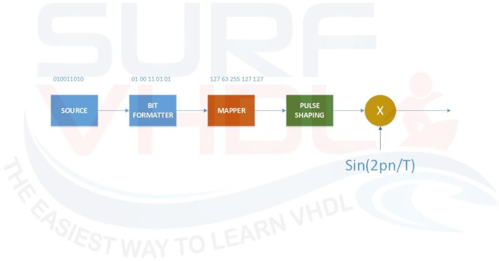
A typical architecture of a modulator is reported in Figure 1
From the left:
- Digital source
- Bit-formatter
- Mapper
- Low-pass interpolator shaping filter
- Optional Up-converter
The digital source can be either internal or external and provides the serial bit-stream to be transmitted at bit rate Rb. The serial bit-stream is “packetized” into a meta-symbol of two or more bit, two bits in this example. The output frequency of the meta-symbols is Rb/Np, where Np is the number of bit of the meta-symbol. The meta symbols are mapped following the desired modulation scheme.
For ASK example, the input symbol is mapped in an N-BIT discrete amplitude.
In this post, we will focus on the mapper using 2 bit for the input meta-symbol and 8 bit for mapper output.
VHDL implementation of ASK mapper
The mapper can receive a 2-bit input i.e. four different meta symbols value:
- 00
- 01
- 10
- 11
The meta-symbol will be mapped into an 8-bit amplitude. The mapping scheme can be decided to maximize the channel efficiency. In this example, we will map the 4 values into 4 different equally distributed intervals. For 8 bit mapping, the possible values are 0, 1, .. 255. Dividing the interval 0..255 in 4 we get 256/4 = 64
- 00 => 63
- 01=> 127
- 10 => 191
- 11 => 255
A possible VHDL code implementation is given below:
library ieee;
use ieee.std_logic_1164.all;
use ieee.numeric_std.all;

entity mapper_ask is
port (
  i_clk                       : in  std_logic;
  i_rstb                      : in  std_logic;
  i_meta_sym                  : in  std_logic_vector(1 downto 0);
  o_mapper                    : out std_logic_vector(7 downto 0));
end mapper_ask;

architecture rtl of mapper_ask is
type t_mapper_table is array(0 to 3) of integer range 0 to 255;
constant mapper_table              : t_mapper_table := (
   63,
  127,
  191,
  255);

signal r_meta_sym                  : integer range 0 to 3; -- used as mapper_table pointer

begin

p_mapper_ask : process(i_clk,i_rstb)
begin
  if(i_rstb='0') then
    r_meta_sym        <= 0;
    o_mapper          <= (others=>'0');
  elsif(rising_edge(i_clk)) then
    r_meta_sym        <= to_integer(unsigned(i_meta_sym));
    o_mapper          <= std_logic_vector(to_unsigned(mapper_table(r_meta_sym),8));
  end if;
end process p_mapper_ask;

end rtl;
VHDL Code for the ASK mapper
The output pattern is stored in the LUT “mapper_table”. If you need different or programmable mapping pattern the solution can be:
- Use an internal dual-port RAM
- Use a set of register
The dual port RAM approach is adopted when the number of mapper symbols is huge (greater than 8 – 10 or more), the register is used otherwise.
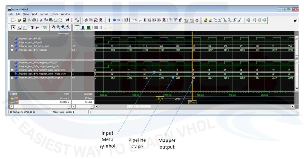
In Figure2 is reported a simulation of the mapper behavior when the input meta-symbol is cycling 0,1,2,3,0,…
Simplified implementation of ASK modulator
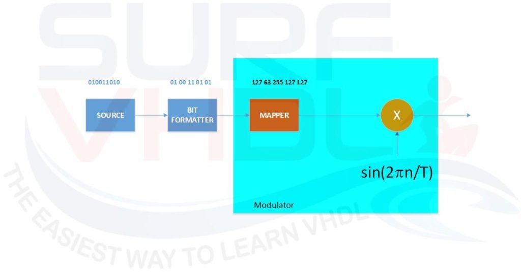
In Figure 3 is shown a simplified architecture of an ASK modulator. In the architecture, no shaping filter is present. The modulator is implemented using a Mapper, and up-converter. The up-conversion is implementer multiplying the mapper output with a digital generated sine waveform. In the example, we will use the dds_sine sine waveform generator implemented in this post.
The VHDL code of ASK modulator multiplies the mapper output by sine wave generated by dds_sine in the process “p_mapper_ask_simple”. When you multiply two integer number of N and M bit, the result is N+M bit. In this case, the mapper output is 8 bit unsigned, so if we want to multiply two number the first signed (sine wave) by the second unsigned (the mapper output) we need to add the sign bit to the unsigned number. Of course, the sign bit will be zero because the mapper output is always positive. In this case, the result will be N+M+1 as in line 66 of the VHDL code for the modulator below.
library ieee;
use ieee.std_logic_1164.all;
use ieee.numeric_std.all;

entity modulator_ask_simple is
port (
  i_clk                       : in  std_logic;
  i_rstb                      : in  std_logic;
  i_sync_reset                : in  std_logic;
  i_fcw                       : in  std_logic_vector(31 downto 0);
  i_start_phase               : in  std_logic_vector(31 downto 0);
  i_meta_sym                  : in  std_logic_vector( 1 downto 0);
  o_molulator                 : out std_logic_vector(11 downto 0));
end modulator_ask_simple;

architecture rtl of modulator_ask_simple is

component mapper_ask
port (
  i_clk                       : in  std_logic;
  i_rstb                      : in  std_logic;
  i_meta_sym                  : in  std_logic_vector(1 downto 0);
  o_mapper                    : out std_logic_vector(7 downto 0));
end component;

component dds_sine
port(
  i_clk          : in  std_logic;
  i_rstb         : in  std_logic;
  i_sync_reset   : in  std_logic;
  i_fcw          : in  std_logic_vector(31 downto 0);
  i_start_phase  : in  std_logic_vector(31 downto 0);
  o_sine         : out std_logic_vector(13 downto 0));
end component;

signal w_sine                      : std_logic_vector(13 downto 0);
signal w_mapper                    : std_logic_vector( 7 downto 0);
signal r_molulator                 : signed(11 downto 0);
signal r_upconverted               : signed(22 downto 0); -- 14 + 8 + 1 bit sign always '0'

begin
o_molulator     <= std_logic_vector(r_molulator);

u_mapper_ask : mapper_ask
port map(
  i_clk                       => i_clk                       ,
  i_rstb                      => i_rstb                      ,
  i_meta_sym                  => i_meta_sym                  ,
  o_mapper                    => w_mapper                    );

u_dds_sine : dds_sine
port map(
  i_clk          => i_clk          ,
  i_rstb         => i_rstb         ,
  i_sync_reset   => i_sync_reset   ,
  i_fcw          => i_fcw          ,
  i_start_phase  => i_start_phase  ,
  o_sine         => w_sine         );

p_modulator_ask_simple : process(i_clk,i_rstb)
begin
  if(i_rstb='0') then
    r_upconverted          <= (others=>'0');
    r_molulator            <= (others=>'0');
  elsif(rising_edge(i_clk)) then
    r_upconverted          <= signed(w_sine) * signed('0'&w_mapper);
    -- 12 MSB; bit 22 and bit 21 are always the same
    r_molulator            <= r_upconverted(21 downto 10);
  end if;
end process p_modulator_ask_simple;

end rtl;
VHDL code for a simplified ASK modulator
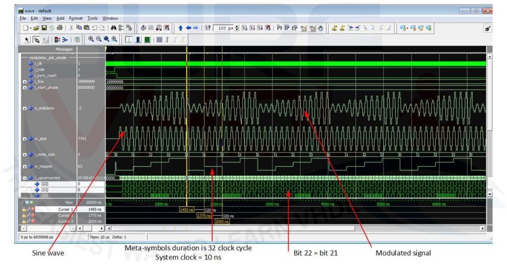
Since the modulator output is 12 bit, we need to take the most significant bit of the multiplication. In this case, we need to pay attention, the first two MSB of the multiplication result are always equal since we have added the sign bit equal to zero to the mapper output.
The output bit selection will be as line 68 where we select bit 21 down to 10 i.e. the instead of 22 down to 11 because of bit 22 and bit 21 are always the same as clear in the simulation results of FIGURE where the bit 22 and bit 21 of the “r_upconverted” signals are always the same.
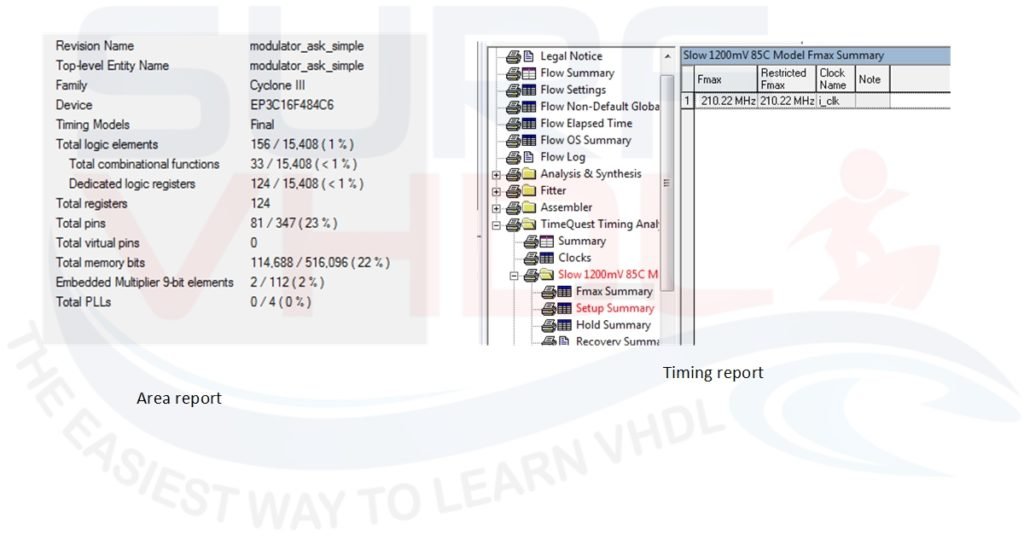
Layout on FPGA
In #Figure 5 is reported the layout report of the modulator implemented above. The FPGA is the Cyclone III present in the Altera DE0 board. As clear from the report the modulator uses the internal RAM to implement the sine wave for the up-conversion and the resource required are low: less than 1% of the (small) FPGA. The working frequency is about 200 MHz.
Conclusion
In this post, we developed a simple APK modulator in VHDL. The VHDL code example for the modulator has been simulated and implemented in a Cyclone III Altera FPGA. You can use this baseline to implement your custom digital modulator in VHDL.
Reference
[1] Digital Modulation in Communications Systems — An Introduction
[2] Understanding Modern Digital Modulation Techniques
[3] Introduction to Digital Modulation
If you appreciated this post, please help us to share it with your friend.
[social_sharing style=”style-7″ fb_like_url=”https://surf-vhdl.com/implement-digital-ask-modulator-in-vhdl” fb_color=”light” fb_lang=”en_US” fb_text=”like” fb_button_text=”Share” tw_lang=”en” tw_url=”https://surf-vhdl.com/implement-digital-ask-modulator-in-vhdl” tw_button_text=”Share” g_url=”https://surf-vhdl.com/implement-digital-ask-modulator-in-vhdl” g_lang=”en-GB” g_button_text=”Share” linkedin_url=”https://surf-vhdl.com/implement-digital-ask-modulator-in-vhdl” linkedin_lang=”en_US” alignment=”center”]
If you need to contact us, please write to: surf.vhdl@gmail.com
We appreciate any of your comment, please post below:
Many thanks for this simplified course
You are welcome!
Best tutorial I have found so far.
Do you have any tutorial for Implementation of BPSK modulator ,It would be really helpful if you could share it to me.
I will write a post on this topic in the next days,
stay tuned!
where do i found the component dds_sine? i am not able to find it
it is linked into the post, btw here the link
http://surf-vhdl.com/how-to-implement-sinusoidal-dds-vhdl/
I’m trying to implement QPSK modulation in VHDL. I have no idea about how to split the incoming data bits into odd and even bits. please help me.
just assign I,Q value to your mapper, for istance:
00 => A0 => I= +A, Q=+A
01 => A1 => I= -A; Q=+A
10 => A2 => I= -A; Q=-A
11 => A3 => I= +A; Q=-A
Could you please give me the testbench, please sir
Please share the test bench code for this ASK modulator