Clock and digital design
When you use an FPGA you always need a clock. When you start the debug of your VHDL layout code on FPGA, often your design doesn’t work as it should!
It’ the hardware my friend!
Digital design has a big advantage w.r.t analog design:
if you implement a (good) synchronous design and simulate it, you are very confident that the design can work as it should.
But the reality is different!
I have a bad news when you start to debug your design on FPGA it always doesn’t work… Did it happen to you?

There is also a good news… If you did a good simulation of your digital design, often the problems you get during the test on a board are of the same type:
- you didn’t handle the reset pin
- the clock signal is absent or of a wrong value
Maybe you are thinking… it is not possible that the main errors are the clock and reset!
Well, if you did simulate your VHDL design, and you did respect the golden rules for a digital design (you can find some example and the available courses here) external reset and clock are often the main issues of your design!
How can we detect the clock?
For the reset pin, the solution is very simple: you can map reset to an output pin connected to a LED so you can check if the reset signal is working fine…
What about the clock?
Here the issue is a bit different. The clock is a periodic signal changing very fast, so you cannot directly connect to a LED but…. if you divide the clock rate to a “human” frequency you can use it to blink a LED.
I mean, connect the clock to a module that implements a counter to generate a slow signal that can drive a LED for instance at the toggling rate of one second. Doing this you can monitor if your clock is present.
It is a good solution but…. How can you measure the clock frequency? You can guess something from the blinking rate but is only a rough estimation.
Click Here to enroll the free course
“How To Measure Clock Frequency in FPGA”
Compute the clock frequency digitally
If we need to verify the clock frequency, we can
- use an oscilloscope
- count the clock rate
The first solution maybe didn’t need a blog post or further explanation
So let’s see how to implement a clock frequency counter.
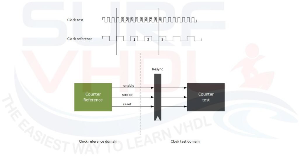
The basic idea is reported in the figure

As you can see, we use a reference clock to detect a test clock.
The reference clock counts for a fixed number clock cycles. This defines a time interval. For instances if the test clock is 50 MHz, i.e. 20 ns, the counting value is 2^12, counting time period is:
20 ns * 2^12 = 81.920ns = 81,920 us
In order to compute the test clock frequency, we need to know how many clock cycles of the test clock are present into the reference interval. So we can use the reference clock counter to start and stop the clock test counter.
Maybe an example should clarify:
- REF clock = 50 MHz (20 ns)
- REF clock count = 2^12
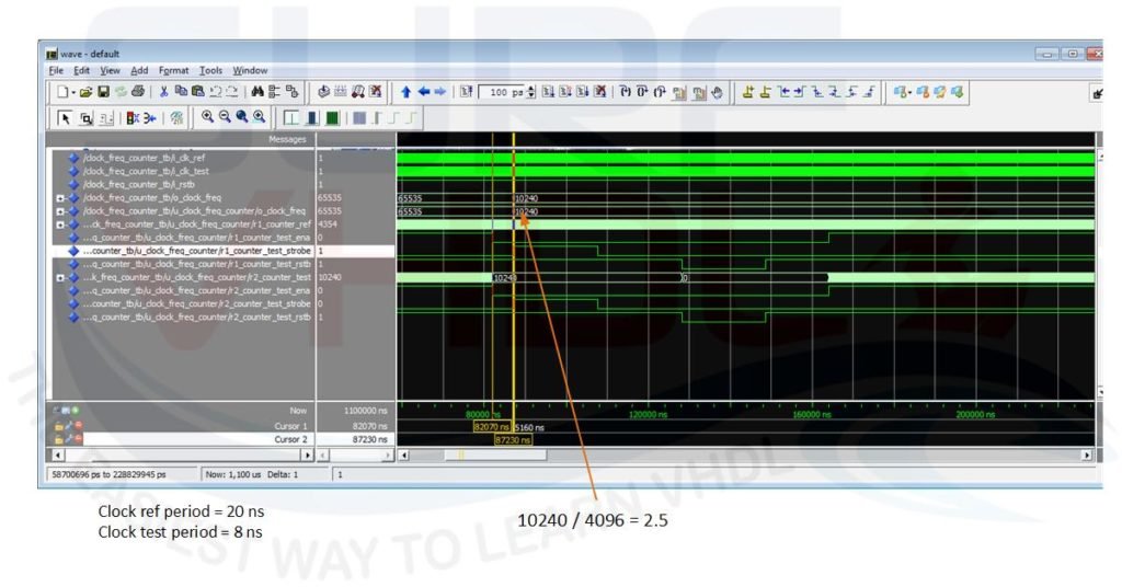
every 2^12 reference clock counting the test clock counts for 10240 as in simulation reported in Figure3
The test clock frequency will be:
10240/4096* 50 MHz = 2.5*50 = 125 MHz (8 ns)

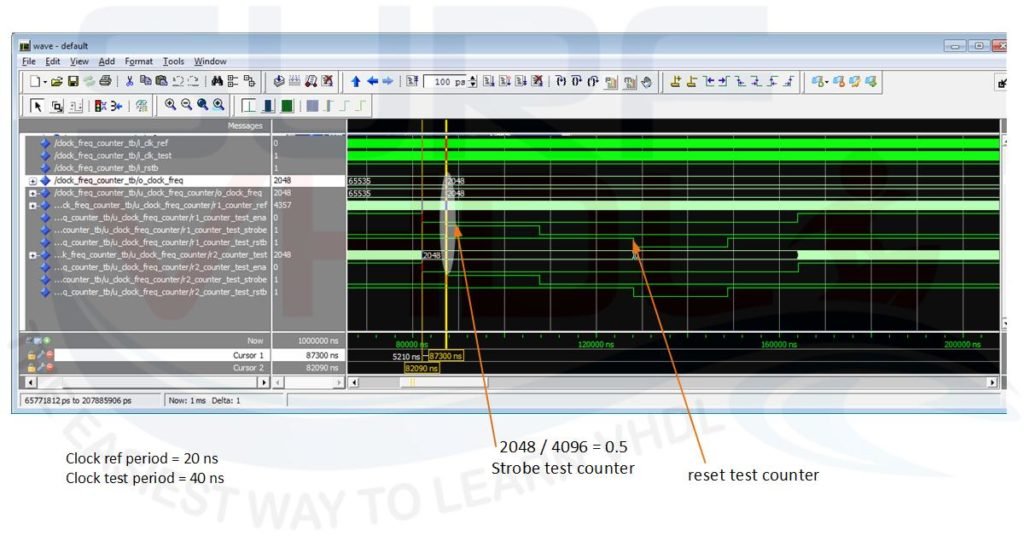
A second example, if test clock counter counts for 2048
The test clock frequency will be: 2048/4096* 50 = 0.5 * 50 = 25 MHz (40 ns)
as in simulation reported in Figure4

VHDL code for the clock frequency counter
As we saw, the basic idea in clock frequency computing is very simple, but we have to pay attention in implementing the VHDL component.
As you can see the two clock, reference clock, and test clock, are asynchronous.
When we have to handle two different asynchronous clock domain we need to pay attention in clock domain crossing (CDC)
In the Figure2, it is clear that the control signal for the test counter is resynchronized in the test clock domain in order to control the counter test. If you do not perform such re-synchronization the layout tool could implement the correct control logic for the clock test domain.
library ieee;
use ieee.std_logic_1164.all;
use ieee.numeric_std.all;

entity clock_freq_counter is
port (
  i_clk_ref            : in  std_logic;
  i_clk_test           : in  std_logic;
  i_rstb               : in  std_logic;
  o_clock_freq         : out std_logic_vector(15 downto 0));
end clock_freq_counter;

architecture rtl of clock_freq_counter is

-- r1_  register con clock reference domain
-- r2_  register con clock test domain

--  CLOCK REFERENCE signal declaration
signal r1_counter_ref              : unsigned(12 downto 0);  -- 12+1 bit: extra bit used for test counter control
signal r1_counter_test_ena         : std_logic;
signal r1_counter_test_strobe      : std_logic;
signal r1_counter_test_rstb        : std_logic;
--  CLOCK TEST signal declaration
signal r2_counter_test             : unsigned(15 downto 0); -- clock test can be up-to 16 times clock ref
signal r2_counter_test_ena         : std_logic;
signal r2_counter_test_strobe      : std_logic;
signal r2_counter_test_rstb        : std_logic;

begin
--  CLOCK REFERENCE domain
p_counter_ref : process (i_rstb,i_clk_ref)
begin
  if(i_rstb='0') then
    r1_counter_ref                 <= (others=>'0');
    r1_counter_test_ena            <= '0';
    r1_counter_test_strobe         <= '0';
    r1_counter_test_rstb           <= '0';
  elsif(rising_edge(i_clk_ref)) then
    r1_counter_ref            <= r1_counter_ref + 1;  -- free running

    -- use MSB to control test counter
    r1_counter_test_ena       <= not r1_counter_ref(r1_counter_ref'high);

    -- enable storing for 1024 clock cycle after 256 clock cycle
    if(r1_counter_ref>16#1100#) and (r1_counter_ref<16#1500#) then
      r1_counter_test_strobe     <= '1';
    else
      r1_counter_test_strobe     <= '0';
    end if;

    -- enable reset for 1024 clock cycle; after 1024 clock cycle from storing
    if(r1_counter_ref>16#1900#) and (r1_counter_ref<16#1D00#) then
      r1_counter_test_rstb    <= '0';
    else
      r1_counter_test_rstb    <= '1';
    end if;

  end if;
end process p_counter_ref;

------------------------------------------------------------------------------------------------------------------------

p_clk_test_resync : process (i_clk_test)
begin
  if(rising_edge(i_clk_test)) then
    r2_counter_test_ena        <= r1_counter_test_ena     ;
    r2_counter_test_strobe     <= r1_counter_test_strobe  ;
    r2_counter_test_rstb       <= r1_counter_test_rstb    ;
  end if;
end process p_clk_test_resync;

p_counter_test : process (r2_counter_test_rstb,i_clk_test)
begin
  if(r2_counter_test_rstb='0') then
    r2_counter_test         <= (others=>'0');
  elsif(rising_edge(i_clk_test)) then
    if(r2_counter_test_ena='1') then
      r2_counter_test    <= r2_counter_test + 1;
    end if;
  end if;
end process p_counter_test;

p_counter_test_out : process (i_rstb,i_clk_test)
begin
  if(i_rstb='0') then
    o_clock_freq         <= (others=>'1');  -- set all bit to '1' at reset and if test clock is not present
  elsif(rising_edge(i_clk_test)) then
    if(r2_counter_test_strobe='1') then
      o_clock_freq         <= std_logic_vector(r2_counter_test);
    end if;
  end if;
end process p_counter_test_out;

end rtl;
In the VHDL code, the r1_ and r2_ prefixes denote the reference and test clock domain respectively.
As clear the “p_clock_test_resync” process resynchronize the control signal versus the test clock domain, and this guarantee the layout tool to work fine in the test clock domain.
In the VHDL code for clock counter, the reference counter is set to 12 bit and the test counter is 16 bit: the test clock can run up to 16 times (16-12 bit: 2^4 = 16) faster than the reference clock. If the test clock runs faster than 16 times, the 16-bit counter will wrap around and the frequency we detect the wrong frequency.
In this case, if we know the point we can compensate the wrap around in the clock computation equation adding 2^16 to the clock test counter.
For instance, reference clock = 1 MHz, test clock = 18 MHz
Every 2^12 clock reference cycle, the test clock counter will count
2^12*18 = 73728
but if we are using a 16 bit counter the value we get will be:
73728-65536 = 8192
In this case, if we do not take into account the counter wrapping the frequency we are computing will be
2^12/8192 * 1 MHz = 0.5 MHz
instead of 18 MHz!
Clock Domain Crossing strategy
In the VHDL code of the clock frequency counter, we are using an extra bit on the reference counter. This trick is used to guarantee the correct clock domain crossing. As you can see, the strobe signal will be stable for 256 clock reference cycle then the reset signal will be asserted after 1024 clock reference cycle after the strobe signal de-assertion.
Using this strategy, we will assure that our clock frequency counter can work also with test clock slower than reference clock. How slow?
In this implementation 256 times slower!
In the simulation of Figure3 and Figure4, there are some examples that simulate test clock faster than reference and test clock slower than reference clock.
Click Here to enroll the free course
“How To Measure Clock Frequency in FPGA”
Clock Counter VHDL code live demo
In the video below you can watch an example of clock frequency counter implementation.
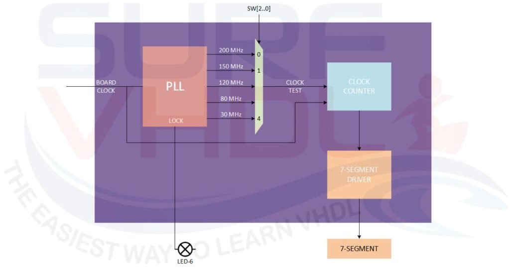
The design is implemented on a DE0 Altera board where we use an internal PLL to generate different internal clocks selected by dip switch as clarified in Figure5

The selected clock will be used as test clock. The reference clock is the 50 MHz board clock.
In the seven segment display is reported the clock frequency counter value of hexadecimal value.
The clock frequency estimated will be:
HEX_VALUE/2^12 * 50 MHz
In the video to can watch the implementation
[video_player type=”youtube” youtube_remove_logo=”Y” width=”560″ height=”315″ align=”center” margin_top=”0″ margin_bottom=”20″]aHR0cHM6Ly95b3V0dS5iZS9oeTYwMUw0djJrTQ==[/video_player]
If you appreciated this post, please help us to share it with your friend.
[social_sharing style=”style-7″ fb_like_url=”https://surf-vhdl.com/how-to-compute-the-frequency-of-a-clock” fb_color=”light” fb_lang=”en_US” fb_text=”like” fb_button_text=”Share” tw_lang=”en” tw_url=”https://surf-vhdl.com/how-to-compute-the-frequency-of-a-clock” tw_button_text=”Share” g_url=”https://surf-vhdl.com/how-to-compute-the-frequency-of-a-clock” g_lang=”en-GB” g_button_text=”Share” linkedin_url=”https://surf-vhdl.com/how-to-compute-the-frequency-of-a-clock” linkedin_lang=”en_US” alignment=”center”]
If you need to contact us, please write to: surf.vhdl@gmail.com
We appreciate any of your comment, please post below:
I need help on a project mine audio system recorder in vhdl and nexys4ddr
I need to have a clock cycle delay for the 40 MHz clk.
How can I do it ?
what do you mean?
Can you explain better?
Hey! Great tutorial! Would you mind possibly posting the test bench you used?
thank you for your feedback!
If you enroll in the free course you can download the files
Cheers!
Veriog code to find the frequency
// Description : This module measures the priod of the connected signal //
// : Reference clock is 125Mhz/8ns //
// //
// Calculation : osc_out[15] generates unexpected flag //
// : osc_out[14:0]/16 is the priod in ns //
// : accuracy is 0.0625ns //
// //
// instance template: //
// oscilloscope #(.EXP_VALUE (16’h008)) oscilloscope_ (.clk_ref_125(clk_eth_f4),.clk_in(clk_ila),.osc_out(scp_ila)); //
// //
`timescale 1ns/1ps
module oscilloscope
#(
parameter EXP_VALUE = 12’h057
)
(
input wire clk_ref_125 ,
input wire clk_in,
output logic [15:0] osc_out = 0 // o – muxed signature from different egress
);
// Signal declarations
logic [6:0] divided_clk = 0;
logic [14:0] count_nxt ;
logic [14:0] count_ff = 0;
logic [14:0] period ;
// divided the clock to 8×16=128 since 8ns reference and 16 bit decimal
always @ (posedge clk_in)
divided_clk <= divided_clk + 1;
// generate pulse from the divided_clk[6] after sync to clk_ref_125 TODO
assign measure_pulse =
// flops
always @ (posedge clk_ref_125) begin
osc_out[14:0] <= period;
count_ff <= count_nxt;
end
// count period and restart at pulse
always_comb begin
count_nxt = count_ff;
period = osc_out[14:0];
// store and restart
if (measure_pulse) begin // —-
// increment only if not overflowing
if (!(&count_nxt)) begin // —-
// generate the higher bit as a flag
if (EXP_VALUE == (period[14:4]+period[3])) begin // —-
else begin // —-
end // always
endmodule
hello, nice post!
I am curious… is it feasible to improve resolution like for 16 bits to 32 bits?
Thank you
yes, just use 32 bit in the counter
Hi,
Thank you for sharing knowledge.
I am just wondering how I’d like to develop a tachometer using the MachX03LF FPGA board and display the pulse rate on the display. I use a 12MHz clock and have to use a small frequency so I used clock register (22) details of the code as below. Any advice would be great thank you.
Cheers, Jack
library ieee;
use ieee.std_logic_1164.all; — use stand logic
use ieee.std_logic_arith.all;
use ieee.std_logic_unsigned.all;
–library MACHXO3;
–use MACHXO3.all;
entity testCC2510 is
port(clkin: in std_logic;
reset: in std_logic;
SW4: in std_logic;
LED: out std_logic_vector(7 downto 0);
com: out std_logic;
D2_out: out std_logic_vector(6 downto 0);
D1_out: out std_logic_vector(6 downto 0);
D0_out: out std_logic_vector(6 downto 0);
DP1_out: out std_logic;
DP2_out: out std_logic;
LED_out: out std_logic_vector(7 downto 0));
— define the pin connections
attribute loc:string;
attribute loc of clkin: signal is “C8”;
attribute loc of D0_out: signal is “R13,T14,T12,R11,T11,M11,N10”;
attribute loc of D1_out: signal is “R10,P10,T10,R9,T9,N9,M8”;
attribute loc of D2_out: signal is “M6,L8,T8,P8,R7,R8,T7”;
attribute loc of com: signal is “P7”;
attribute loc of reset: signal is “G2”;–was K1
attribute loc of SW4: signal is “N1”;
attribute loc of DP1_out: signal is “P9”;
attribute loc of DP2_out: signal is “P11”;
attribute loc of LED_out: signal is “F3,D3,G3,C2,F5,E3,B1,C1″;
end;
architecture arch_testCC2510 of testCC2510 is
component SevenSeg
port(LEDin: in integer;
SevSegout: out std_logic_vector);
end component;
signal clkreg : std_logic_vector(31 downto 0);
signal c_clk: std_logic;
signal dig2: std_logic_vector(6 downto 0):=”1111111”;
signal dig1: std_logic_vector(6 downto 0);
signal dig0: std_logic_vector(6 downto 0);
signal DP1: std_logic:=’1′;
signal DP2: std_logic:=’1′;
signal count0: integer range 0 to 9;
signal count1: integer range 0 to 9;
signal oscpin: std_logic;
begin
clk1:process(clkin)
begin
if (clkin’event and clkin = ‘1’) then
clkreg <= clkreg+X"00000001";
end if;
c_clk <= clkreg(22);
oscpin <= clkreg(15);
end process clk1;
lcdmod:process(oscpin)
begin
if (oscpin='1') then
D2_out<=dig2;
D1_out<=dig1;
D0_out<=dig0;
DP1_out<=DP1;
DP2_out<=DP2;
else
D2_out<= not dig2;
D1_out<= not dig1;
D0_out<= not dig0;
DP1_out<= not DP1;
DP2_out<= not DP2;
end if;
com<=oscpin;
end process;
DD0:SevenSeg port map(count0,dig0);
DD1:SevenSeg port map(count1,dig1);
p_counter: process
begin
wait until rising_edge(c_clk);
if (SW4='1') then
if ((count1=9) and (count0=9)) then
count1<=0;
count0<=0;
elsif(count0=9) then
count1<=count1+1;
count0<=0;
else
count0<=count0+1;
end if;
else
if((count1=0) and (count0=0)) then
count1<=9;
count0<=9;
elsif(count0=0) then
count1<=count1-1;
count0<=9;
else
count0<=count0-1;
end if;
end if;
if reset = '0' then
count0<=0;
count1<=0;
end if;
end process p_counter;
LED_out SevSegoutSevSegoutSevSegoutSevSegoutSevSegoutSevSegoutSevSegoutSevSegoutSevSegoutSevSegout<="0000100";
end case Lab0;
end process;
end SevenSeg_arch;
Great work!
Why did you divide by 4096?
just an example