Parallelize after serializing
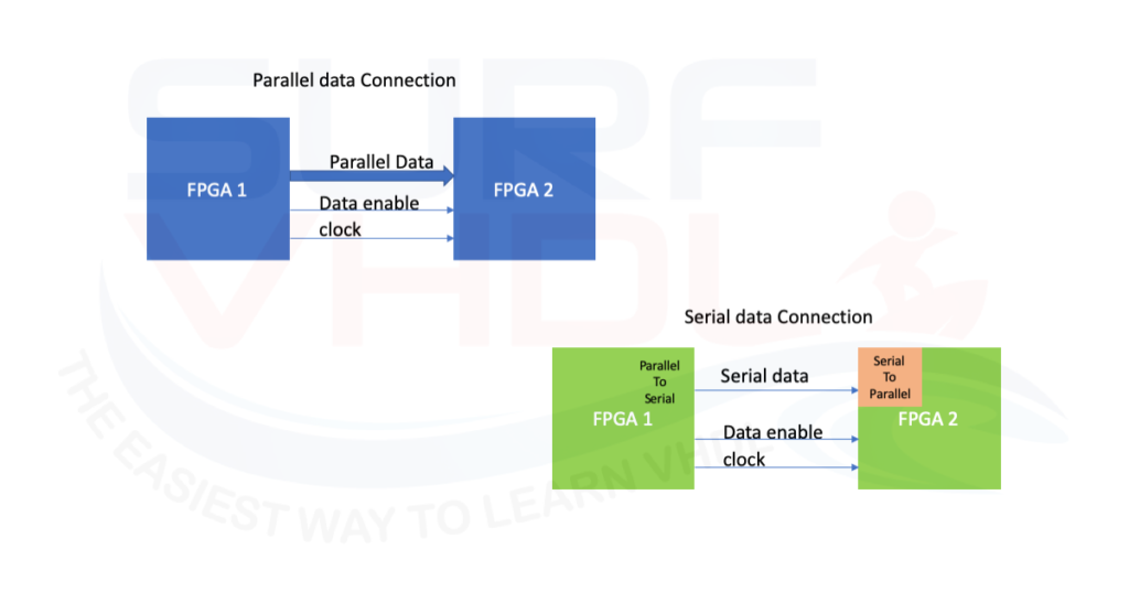
In this post, we analyzed the VHDL code for a parallel to serial converter. This approach is very useful in interfacing different devices. Many FPGA vendors like Xilinx, Intel/Altera give us the possibility to use internal serializer-deserializer such as a serial transceiver. In this post, we want to implement the complementary interface of the parallel to serial interface. We will see how to implement the VHDL code for a serial to parallel interface in order to get back the parallel data bus we sent in the transmitter device. In other words, we will implement the VHDL block in the of the bottom right of Figure1

Serial to Parallel converter VHDL code example
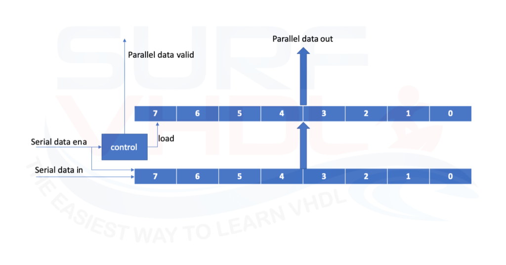
Let assume the parallel data bus of the Serial to Parallel converter to be N bit. The parallel output to the module will be available every N clock cycle since N clock cycles are needed to load the shift register that provided the parallel output as in Figure2

An example of Serial to Parallel converter VHDL code is given below:
 library ieee;
use ieee.std_logic_1164.all;

entity serial2parallel is
generic(
	G_N               : integer:=8 );
port (
	i_clk                          : in  std_logic;
	i_rstb                         : in  std_logic;
	i_sync_reset                   : in  std_logic;
	i_data_ena                     : in  std_logic;
	i_data                         : in  std_logic;
	o_data_valid                   : out std_logic;
	o_data                         : out std_logic_vector(G_N-1 downto 0));
end serial2parallel;

architecture rtl of serial2parallel is
signal r_data_enable                  : std_logic;
signal r_data                         : std_logic_vector(G_N-1 downto 0);
signal r_count                        : integer range 0 to G_N-1;

begin

p_serial2parallel : process(i_clk,i_rstb)
begin
	if(i_rstb='0') then
		r_data_enable        <= '0';
		r_count              <= 0;
		r_data               <= (others=>'0');
		o_data_valid         <= '0';
		o_data               <= (others=>'0');
	elsif(rising_edge(i_clk)) then
		o_data_valid         <= r_data_enable;
		if(r_data_enable='1') then
			o_data         <= r_data;
		end if;

		if(i_sync_reset='1') then
			r_count        <= 0;
			r_data_enable  <= '0';
		elsif(i_data_ena='1') then
			r_data         <= r_data(G_N-2 downto 0)&i_data;
			if(r_count>=G_N-1) then
				r_count        <= 0;
				r_data_enable  <= '1';
			else
				r_count        <= r_count + 1;
				r_data_enable  <= '0';
			end if;
		else
			r_data_enable  <= '0';
		end if;
	end if;
end process p_serial2parallel;

end rtl;
An example of Serial to Parallel converter VHDL code is given below:
In the VHDL code every G_N clock cycles the counter enable the parallel output register and provides the parallel data output and the relative enable pulse. With respect to the parallel to serial converter in this case no error detection logic is present. The output parallel data rate is slower than the input serial data rate, so no error condition can occur.
Serial to Parallel converter VHDL simulation results
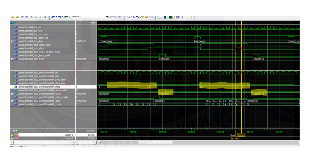
In the simulation of all the figures below, the clock is set to 10 ns, so 80 ns mean 8 clock cycles.
In Figure4 is reported a simulation of the serial to parallel converter VHDL code above. In order to realize the test bench, the parallel to serial converter of this post is used. As a
In Figure4 is reported a simulation of the serial to parallel converter VHDL code. As clear the serial input to be parallelized is re-serialized in the byte signal.

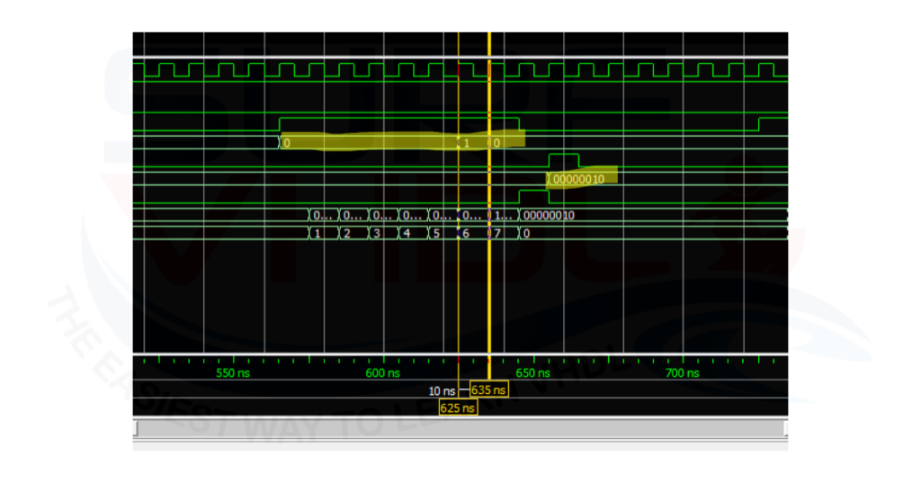
In Figure5 is highlighted the ZOOM-IN of the serial conversion of the serial pattern “00000010”.

Conclusion
In this post, we implemented a simple example of a serial to parallel VHDL code. Such a conversion strategy can be used when we need to connect two different devices like two FPGA, and we need to minimize the connection wires. Using a serial connection, we can minimize the number of connection wires, minimizing also the skew problem on the connection itself. This module can be used in conjunction with the serial to parallel converter discussed in this post.
Hello,
I want to implement from an ASI stream a parallel stream.
can you help me?
Kind regards