

Fixed vs floating point representation
When we use FPGA, we need to deal with fixed-point arithmetic. Even if newer FPGAs like Intel Stratix 10 implement floating-point multipliers, if we need to implement Digital Signal Processing (DSP) in FPGA we have to use fixed-point arithmetic.
Many people have serious problems dealing with fixed-point binary representation or quantization of a floating-point value into fixed-point.
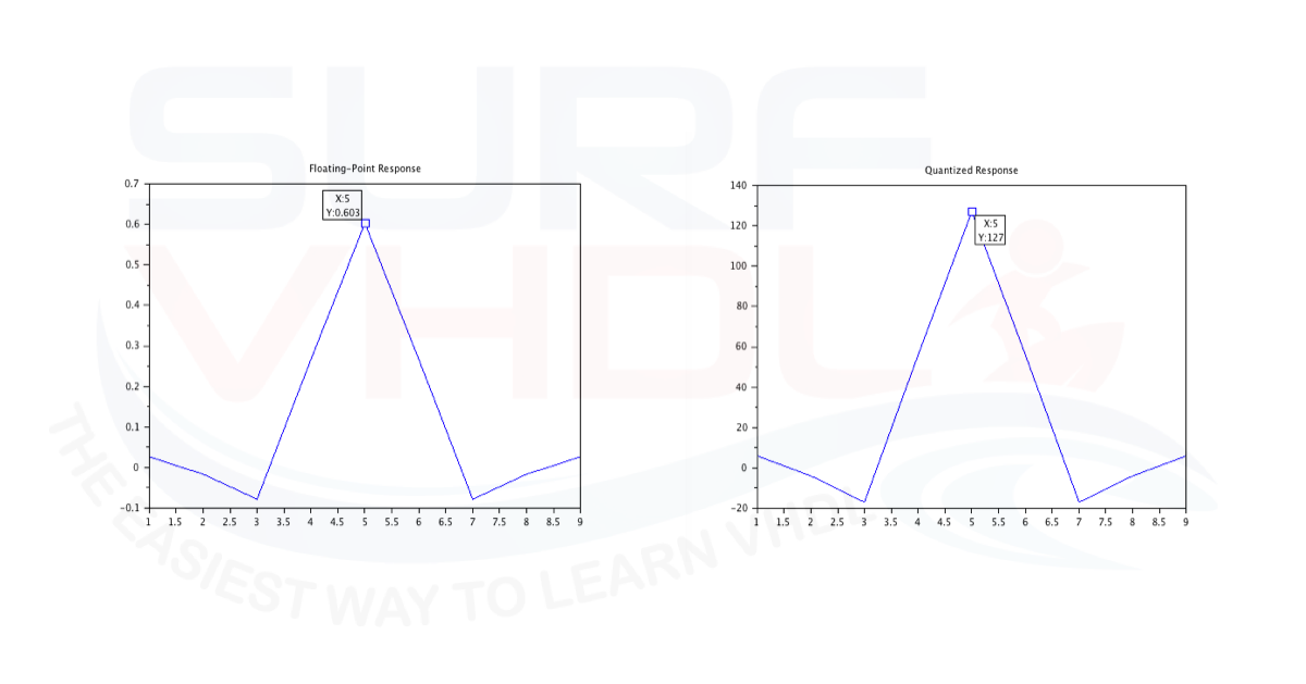
Figure 1 – Floating-point vs Quantized FIR impulse response
In this post, I explained how to divide a number by a constant in VHDL. Of course, you need to have the basics of binary number representation that you can find in this post.
Fixed-point representation introduction
In VHDL, we generally use binary signed fixed-point number representation. Using the signed binary representation, we can take advantage of the standard library for the
- addition
- subtraction
- multiplication
Just to be clear, you can use also unsigned binary number representation, but if you are implementing a DSP architecture, it is very likely that you need to deal with positive and negative numbers.
In signed fixed-point representation we need to define the number of bits we are using to represent our number.
For example, if we use 8 bits, we can represent the integer numbers from -128 to +127. The MSB is the sign bit (1 = negative), and the remaining 7 bits represent the magnitude in two’s complement.
i.e. -2^(N-1) <= Number <= +(2^(N-1))-1
where N=8.
In the signed representation there is one more negative number than positive.
If we deal with unsigned binary number the range will be
Number <= +(2^N)-1
For example, for 8-bit number 0..255
Fixed-point representation of an FIR coefficient
What we are going to say in this section is valid for any kind of binary quantization.
When we need to quantize the impulse response of an FIR filter we need to:
- set the number of bits to represent the coefficient
- scale the floating point of the impulse response w.r.t. the maximum value
- convert the scaled coefficient to a fixed-point value
You can use a MATLAB script, a Scilab script, Excel, or your calculator to implement these steps.
Below are the commands to quantize your floating-point FIR impulse response (coefficient) in Scilab. The commands can be used in MATLAB too.
 N = 8;
 MaxPos = (2^(N-1))-1;
 MaxNeg = (2^(N-1));

h  = [

   0.02674
  -0.01668
  -0.07822
   0.26686
   0.60294
   0.26686
  -0.07822
  -0.01668
   0.02674];

hNorm = h./max(h)

ptrNeg = find(hNorm<0);

hQ = hNorm .* MaxPos

hQ(ptrNeg) = hNorm(ptrNeg) .* MaxNeg

hQ = round(hQ)

plot(h)
title('Floating-Point Response')

figure
plot(hQ)
title('Quantized Response')
In Figure 1 the floating-point and quantized version of the FIR impulse response.
| Index | Floating-point | Quantized (decimal) | Quantized (binary) | Error |
|---|
In the first highlighted line we are normalizing the impulse response between -1 and +1.
Notice that we are assuming that the maximum value is positive.
Then we find all the indices of negative values.
We are quantizing the positive values by multiplying the normalized impulse response by the maximum positive value.
Then we overwrite the negative quantized values.
Finally, we quantize the coefficient to fixed-point values by rounding the floating-point version.
Using quantized coefficients in VHDL
Once you have the quantized coefficients, you can store them in a constant array and use them in your FIR filter implementation:
type t_coeff is array (0 to 8) of signed(7 downto 0);

constant C_COEFF : t_coeff := (
  to_signed( 3, 8),
  to_signed(-2, 8),
  to_signed(-10, 8),
  to_signed( 34, 8),
  to_signed( 77, 8),
  to_signed( 34, 8),
  to_signed(-10, 8),
  to_signed(-2, 8),
  to_signed( 3, 8));
The quantized values match the rounded output hQ from the Scilab/MATLAB script above, scaled to 8-bit signed representation.
Conclusion
In this post, we learned how to quantize the floating-point impulse response of an FIR filter into fixed-point representation using Scilab (or MATLAB). The resulting coefficients can be directly used in a VHDL design as a constant array.
Remember that the number of bits used for quantization directly impacts both the filter precision and the FPGA resources used. Always verify the filter frequency response after quantization to ensure it still meets your requirements.