
Multipliers in Modern FPGAs
In modern FPGAs, multiplication is implemented using a dedicated hardware resource. Such dedicated hardware resource generally implements 18×18 multiply and accumulate function that can be used for efficient implementation of complex DSP algorithms such as finite impulse response (FIR) filters, infinite impulse response (IIR) filters, and Fast Fourier Transform (FFT) for filtering and image processing applications etc.
The Multiplier-Accumulator blocks have a built-in multiplier and adder, which minimizes the fabric logic required to implement multiplication, multiply-add, and multiply-accumulate (MACC) functions. Implementation of these arithmetic functions results in efficient resource usage and improved performance for DSP applications. In addition to the basic MACC function, DSP algorithms typically need small amounts of RAM for coefficients and larger RAMs for data storage.
The main features of the multiply-accumulate block are:
- Supports 18 × 18 signed multiplication natively.
- Supports 17 × 17 unsigned multiplications.
- Built-in addition, subtraction, and accumulation units to combine multiplication results efficiently.
- Independent third input C with data width completely registered.
- Single-bit input, CARRYIN, from fabric routing.
Of course, these features depend on the technology we are using. Above are described the features that are mainly implemented on every modern FPGA such as Altera Stratix, Xilinx Virtex, Microsemi Smartfusion and so on. Each of these technologies customize the implementation adding different features depending on the type of FPGA you are using.
You can, of course, instantiate multiply-accumulate macros using the core generator of the vendor as follow:
Generate the VHDL/Verilog code for the component
Instantiate the component in your VHDL/Verilog code.
Another solution to use the multiplier hardware macro is to activate the instantiation writing the proper VHDL/Verilog code that triggers the synthesizer the instantiation of hardware macro.
VHDL Implementation of a Signed Multiplier
Here below you can find the template for NxM signed multiplier. If you want to trigger the hardware macro in an efficient way N and M shall be less than the maximum number of bit handled by the hardware multiplier macro. For instance, if the hardware multiplier can work up to 18×18, you can set N and M to be less or equal to 18 bit. Using more than 18 bit the implementation will use more than a multiplier block slowing down the timing performances.
When you multiply two number with N and M bit, the result will be of N+M bit. For instance, if the first multiplicand has 14 bit and the second multiplicand has 13 bit, the result of the multiplication will have 13+14 = 27 bit.
The example below will implement a 13 x 14 bit signed multiplier.
library ieee ;
use ieee.std_logic_1164.all;
use ieee.numeric_std.all;

entity mult_sgn_13x14 is
generic (
  n          : integer:= 13;
  m          : integer:= 14);
port (
  i_clk      : in  std_logic;
  i_rstb     : in  std_logic;
  i_ma       : in  std_logic_vector(12 downto 0);
  i_mb       : in  std_logic_vector(13 downto 0);
  o_m        : out std_logic_vector(26 downto 0));
end mult_sgn_13x14;

architecture rtl of mult_sgn_13x14 is

signal r_ma       : signed(12 downto 0);
signal r_mb       : signed(13 downto 0);
signal r_m        : signed(26 downto 0);

begin

o_m  <= std_logic_vector(r_m);

p_mult : process(i_clk,i_rstb)
begin
  if(i_rstb='0') then
    r_ma       <= (others=>'0');
    r_mb       <= (others=>'0');
    r_m        <= (others=>'0');
  elsif(rising_edge(i_clk)) then
    r_ma       <= signed(i_ma);
    r_mb       <= signed(i_mb);
    r_m        <= r_ma * r_mb;
  end if;
end process p_mult;

end rtl;
VHDL Code for 13×14 signed multiplier
To understand what are the hardware resources relative to the 13×14 multiplier implementation let’s lay out the code on a Cyclone IV FPGA EP4CGX30. This FPGA has 80 multiplier 18×18 that can be used as 160 multiplier 9×9. The synthesizer maps the best hardware macro implementation for your design.
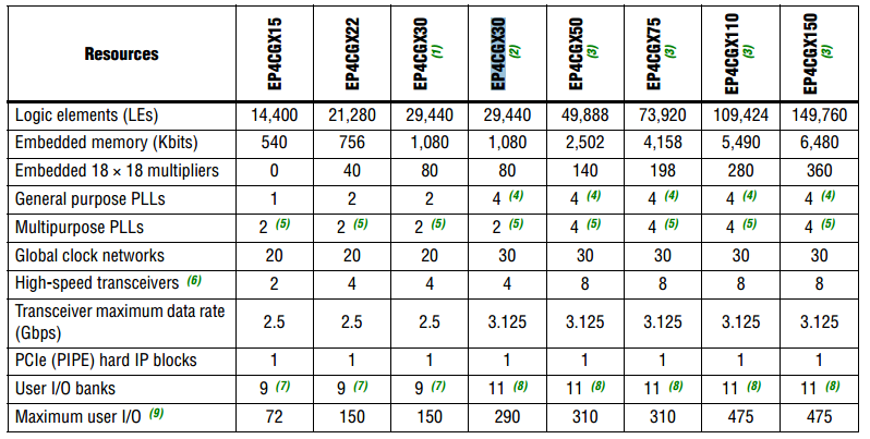
Figure 1 – Cyclone IV resource Table
Figure 1 reports the hardware resources available for the different version of Cyclone IV FPGA. The multiplier has been realized using 2 embedded 9×9 multiplier, as reported on Area report of Figure 2. In the timing report, the maximum clock frequency is 286 MHz.
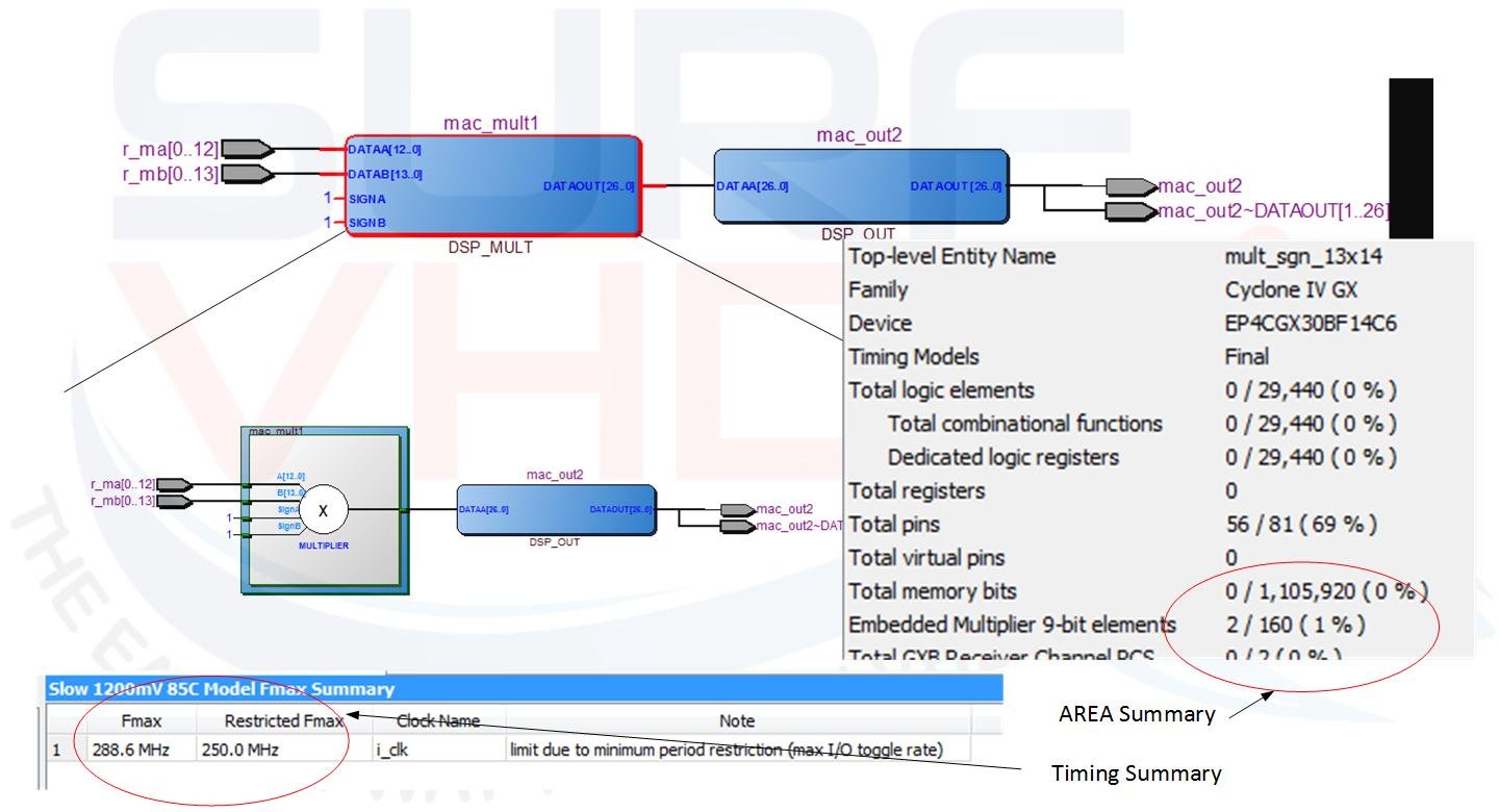
Figure 2 – Implementation on Cyclone IV of 13×14 multiplier
In Figure 3 is reported the Area and Timing report for a 16×16 multiplier. As is clear, the hardware resources for the multipliers are the same of the 13×14 multiplier since the VHDL code trigger the same multiplier hardware macro 18×18.
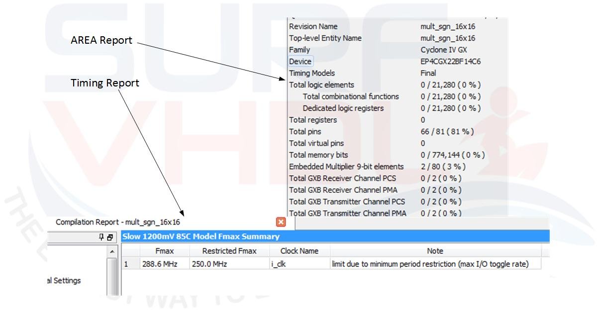
Figure 3 – Cyclone IV Area and Timing report for 16×16 multiplier
Designing a Custom 16×16 Pipelined Multiplier
Taking as reference the previous example, now we are going to implement the pipelined version of the 16×16 multiplier. Let’s refresh the multiplication algorithm: a 16 bit operand can be written as follow:

A[15:0] = (A[15:8] x 2^8) +A[7:0] x 2^0

Es:

48565 = 0xBDB5 = (189 x 256) + 181
So, if we want to multiply two 16-bit operands:
A[15:0] = A[15:8] x 2^8 +A[7:0] x 2^0
B[15:0] = B[15:8] x 2^8 +B[7:0] x 2^0

A[15:0] x B[15:0] = (A[15:8] x 2^8 +A[7:0] x 2^0) x (B[15:8] x 2^8 +B[7:0] x 2^0) =
= A[15:8] x B[15:8] x2^16 +(A[15:8] x B[7:0] + A[7:0] x B[15:8] )x2^8 + A[7:0] x B[7:0]
A[15:0] = 48565 = 0xBDB5 = (189 x 256) + 181
B[15:0] = 29918 = 0x74DE = (116 x 256) + 222

A[15:0] x B[15:0] = 48565 x 29918 =  ((189 x 256) + 181 ) x ((116 x 256) + 222) =
  = (189 x 116) x 65536 + (189x222 + 116x181) x 256 + (181x222) =
  = 21924 x 65536 + (41958+ 20996) x 256 + 40182=
  = 1436811264 + 16116224 + 40182 = 1452967670
The hardware structure for such implementation is reported in Figure 4:
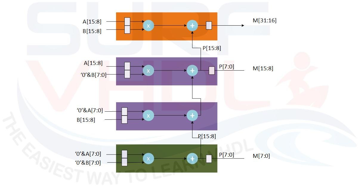
Figure 4 – Architecture of a 16×16 multiplier implemented using partial multiplication
A possible VHDL implementation of Figure 4 is reported below.
library ieee ;
use ieee.std_logic_1164.all;
use ieee.numeric_std.all;

entity mult_sgn_break_16x16 is
port (
  i_clk      : in  std_logic;
  i_rstb     : in  std_logic;
  i_ma       : in  std_logic_vector(15 downto 0);
  i_mb       : in  std_logic_vector(15 downto 0);
  o_m        : out std_logic_vector(31 downto 0));
end mult_sgn_break_16x16;

architecture rtl of mult_sgn_break_16x16 is
-- A[15:0] x B[15:0] = (A[15:8] x B[15:8] x 2^16) +(A[15:8] x B[7:0] + A[7:0] x B[15:8] )x2^8 + A[7:0] x B[7:0]

signal r_ma_hi       : signed( 7 downto 0);
signal r_ma_lo       : signed( 8 downto 0);  -- MSB sign bit
signal r_mb_hi       : signed( 7 downto 0);
signal r_mb_lo       : signed( 8 downto 0);  -- MSB sign bit

signal r_m_hi        : signed(15 downto 0);  -- 8x8 => 16 bit
signal r_m_md        : signed(16 downto 0);  -- 8x8 => 16 bit + 8x8=> 17 bit ==>16 bit + (carry)
signal r_m_lo        : signed(17 downto 0);  -- 9x9 => 16 + 2 sgn bit
signal r_m           : signed(31 downto 0);

begin

o_m  <= std_logic_vector(r_m);

r_m_hi        <= r_ma_hi * r_mb_hi;
r_m_md        <= r_ma_hi * r_mb_lo + r_mb_hi * r_ma_lo;
r_m_lo        <= r_ma_lo * r_mb_lo;

p_mult : process(i_clk,i_rstb)
begin
  if(i_rstb='0') then
    r_ma_hi       <= (others=>'0');
    r_ma_lo       <= (others=>'0');
    r_mb_hi       <= (others=>'0');
    r_mb_lo       <= (others=>'0');
    r_m           <= (others=>'0');
  elsif(rising_edge(i_clk)) then
    r_ma_hi       <= signed(i_ma(15 downto 8));
    r_ma_lo       <= signed('0'&i_ma( 7 downto 0));
    r_mb_hi       <= signed(i_mb(15 downto 8));
    r_mb_lo       <= signed('0'&i_mb( 7 downto 0));
    r_m           <= r_m_hi&"0000000000000000" + resize(r_m_md&"00000000",32) + resize(r_m_lo,32);
  end if;
end process p_mult;

end rtl;
VHDL code for a 16×16 multiplier
Figure 5 reports the area and timing report of VHDL code implementation on Altera Cyclone IV used before. In this case, we are using 4 multipliers 9×9 instead of two and both logic and registers. The timing report is about half the previous and the adder and register are implemented using logic. In the previous example reported in Figure 3 the register and logic was zero since the VHDL code of the multiplier was mapped in the hardware multiplier resource present into the FPGA.
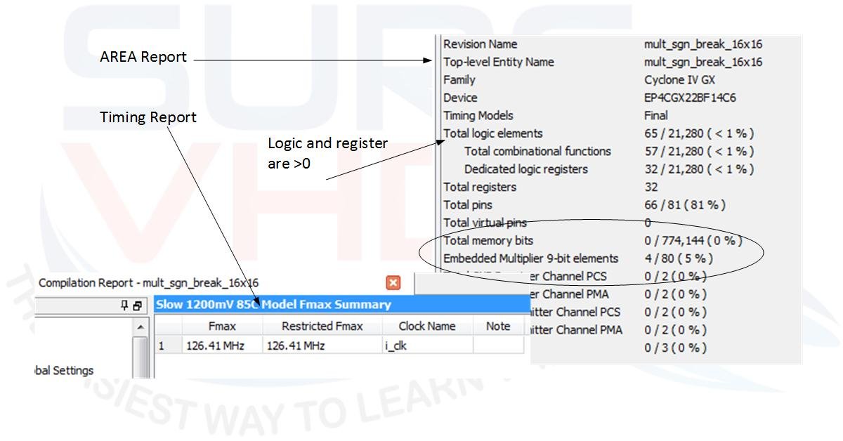
Figure 5 – Area and Timing report for implementation of 16×16 multiplier using 4 multipliers
Starting from the architecture of Figure 4 the pipeline implementation is straightforward. To implement the pipeline into the multiplier architecture, we need to introduce registers to break the combinatorial path of multiplication and addition and compensate the delay added by these registers.
A possible implementation is given in Figure 6. Here the latency of the multiplier is 6 clock cycles.
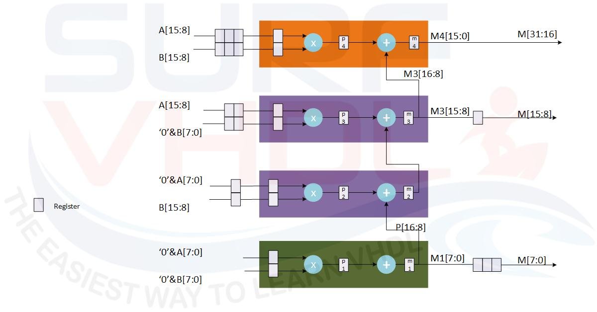
Figure 6 – Pipeline implementation of a 16×16 multiplier
Starting from the architecture of the pipelined multiplier of Figure 6 a possible VHDL implementation of a signed pipeline multiplier is:
library ieee ;
use ieee.std_logic_1164.all;
use ieee.numeric_std.all;

entity mult_sgn_break_pipe2_16x16 is
port (
  i_clk      : in  std_logic;
  i_rstb     : in  std_logic;
  i_ma       : in  std_logic_vector(15 downto 0);
  i_mb       : in  std_logic_vector(15 downto 0);
  o_m        : out std_logic_vector(31 downto 0));
end mult_sgn_break_pipe2_16x16;

architecture rtl of mult_sgn_break_pipe2_16x16 is
-- A[15:8] x B[15:8] x2^16 +(A[15:8] x B[7:0] + A[7:0] x B[15:8] )x2^8 + A[7:0] x B[7:0]

type p_operand is array(0 to 3) of signed( 7 downto 0);
signal p_ma_hi       : p_operand;
signal p_ma_lo       : p_operand;
signal p_mb_hi       : p_operand;
signal p_mb_lo       : p_operand;

signal r_p1          : signed(17 downto 0);  -- 9x9 => 18 bit (16 + 2 sgn bit)
signal r_p2          : signed(16 downto 0);  -- 8x9 => 17 bit (16 + 1 sgn bit)
signal r_p3          : signed(16 downto 0);  -- 8x9 => 17 bit (16 + 1 sgn bit)
signal r_p4          : signed(15 downto 0);  -- 8x8 => 16 bit

signal r_m1          : signed(17 downto 0);  -- 9x9 => 18 bit (16 + 2 sgn bit)
signal r_m2          : signed(16 downto 0);  -- 8x9 => 17 bit (16 + 1 sgn bit)
signal r_m3          : signed(16 downto 0);  -- 8x9 => 17 bit (16 + 1 sgn bit)
signal r_m4          : signed(15 downto 0);  -- 8x8 => 16 bit

signal p_m1          : p_operand;  -- delay compensation
signal p_m3          : signed(7 downto 0);  -- delay compensation

begin

o_m(31 downto 16)  <= std_logic_vector(r_m4(15 downto 0));
o_m(15 downto  8)  <= std_logic_vector(p_m3);
o_m( 7 downto  0)  <= std_logic_vector(p_m1(2));

p_mult : process(i_clk,i_rstb)
begin
  if(i_rstb='0') then
    p_ma_hi       <= (others=>(others=>'0'));
    p_ma_lo       <= (others=>(others=>'0'));
    p_mb_hi       <= (others=>(others=>'0'));
    p_mb_lo       <= (others=>(others=>'0'));
    p_m1          <= (others=>(others=>'0'));
    p_m3          <= (others=>'0');

    r_m1          <= (others=>'0');
    r_m2          <= (others=>'0');
    r_m3          <= (others=>'0');
    r_m4          <= (others=>'0');
    p_m1          <= (others=>(others=>'0'));
    p_m3          <= (others=>'0');
  elsif(rising_edge(i_clk)) then
    p_ma_hi       <= signed(i_ma(15 downto 8))&p_ma_hi(0 to p_ma_hi'length-2);
    p_ma_lo       <= signed(i_ma( 7 downto 0))&p_ma_lo(0 to p_ma_lo'length-2);
    p_mb_hi       <= signed(i_mb(15 downto 8))&p_mb_hi(0 to p_mb_hi'length-2);
    p_mb_lo       <= signed(i_mb( 7 downto 0))&p_mb_lo(0 to p_mb_lo'length-2);
    p_m1          <= r_m1(7 downto 0)&p_m1(0 to p_m1'length-2);
    p_m3          <= r_m3(7 downto 0);

    r_p1          <= signed('0'&p_ma_lo(0)) * signed('0'&p_mb_lo(0));
    r_p2          <= signed('0'&p_ma_lo(1)) * p_mb_hi(1);
    r_p3          <= p_ma_hi(2) * signed('0'&p_mb_lo(2));
    r_p4          <= p_ma_hi(3) * p_mb_hi(3);

    r_m1          <= r_p1;
    r_m2          <= r_p2 + r_m1(16 downto 8);
    r_m3          <= r_p3 + r_m2;
    r_m4          <= r_p4 + r_m3(16 downto 8);
  end if;
end process p_mult;

end rtl;
VHDL code for 16×16 pipeline multiplier
The implementation of the VHDL code of the pipeline multiplier reports the timing characteristic like the implementation of Figure 3 while the area is greater than the implementation of Figure 3.
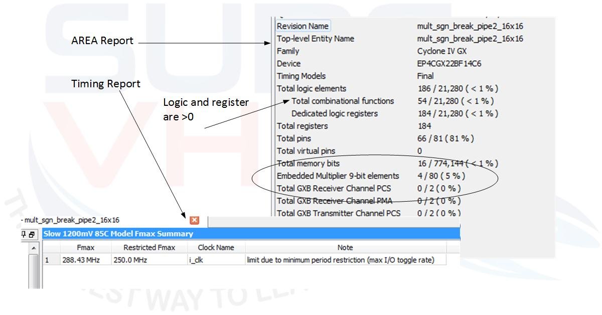
Figure 7 – Area and Timing report for pipeline multiplier 16×16
We can conclude that, for FPGA implementation, if we are using the hardware macro implementation for a multiplier, generally this is the best solution. In ASIC implementation, the pipeline approach can give good result since the same implementation on FPGA report timing performance similar to the optimal implementation of the hardware macro inside the FPGA. In the next section, we will discover a condition where the pipeline multiplier can be used in FPGA too.
When to Use Custom Pipelining in FPGAs
In the previous section, we learned how to pipeline a multiplier. The VHDL of the pipeline multiplier has been evaluated on a Cyclone IV FPGA. As clear from area and timing report there are no significant advantages in writing the pipelined version of a multiplier since we are using the basic multiplier macro primitive. As clear from Figure 3 and Figure 7 the timing is similar while the area is slightly greater than the version without a pipeline. Now we are going to see an example where the pipeline multiplier has better performances than the no pipelined one. Suppose you need a multiplier 35×35. The FPGA we are using supports natively 18×18, so you need to use 2 multiplier 18×18 in order to implement a multiplier 35×35.
The VHDL code for a 35×35 multiplier is:
library IEEE;
use IEEE.std_logic_1164.all;
use IEEE.numeric_std.all;

entity mult_sign_35x35 is
port (
  i_clk      : in  std_logic;
  i_rstb     : in  std_logic;
  i_ma       : in  std_logic_vector(34 downto 0);
  i_mb       : in  std_logic_vector(34 downto 0);
  o_m        : out std_logic_vector(69 downto 0));
end mult_sign_35x35;

architecture rtl of mult_sign_35x35 is

signal r_ma       : signed(34 downto 0);
signal r_mb       : signed(34 downto 0);

begin

p_mult : process(i_clk,i_rstb)
begin
  if(i_rstb='0') then
    r_ma          <= (others=>'0');
    r_mb          <= (others=>'0');
    o_m           <= (others=>'0');
  elsif(rising_edge(i_clk)) then
    r_ma          <= signed(i_ma);
    r_mb          <= signed(i_mb);

    o_m           <= std_logic_vector(r_ma * r_mb);

  end if;
end process p_mult;

end rtl;
VHDL code for 35×35 multiplier
Using a Cyclone IV FPGA the area and timing report are in Figure 8
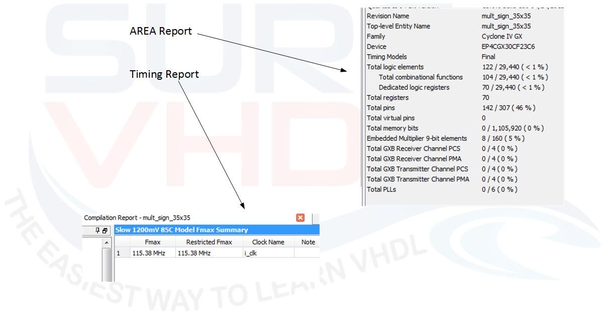
Figure 8 – Area and Timing report of a 35×35 multiplier on a Cyclone IV
In this case, if we want to pipeline the multiply, we can re-write the multiply as:
A[34:0] x B[34:0] =  A[34:17] x 2^17 +A[16:0]) x (B[34:17] x 2^17 +B[16:0]) =
 = A[34:17] x B[34:17] x2^34 +(A[34:17] x B[16:0] + A[16:0] x B[34:17] )x2^17 + A[16:0] x B[16:0]
Following the same rules of the previous section the hardware architecture of the multiplier will be:
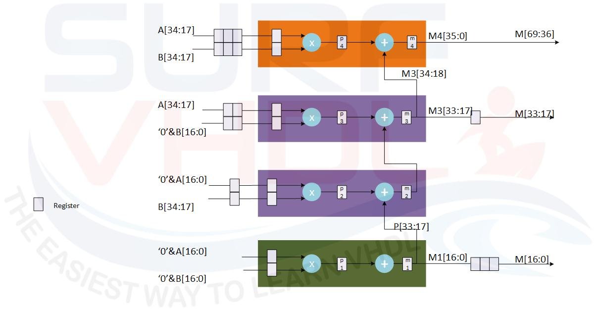
Figure 9 – Area and Timing report of a 35×35 multiplier on a Cyclone IV
The VHDL code for the 35×35 pipelined multiplier can be written following the architecture of Figure 9:
library ieee ;
use ieee.std_logic_1164.all;
use ieee.numeric_std.all;

entity mult_sgn_break_pipe2_35x35 is
port (
  i_clk      : in  std_logic;
  i_rstb     : in  std_logic;
  i_ma       : in  std_logic_vector(34 downto 0);
  i_mb       : in  std_logic_vector(34 downto 0);
  o_m        : out std_logic_vector(69 downto 0));
end mult_sgn_break_pipe2_35x35;

architecture rtl of mult_sgn_break_pipe2_35x35 is
-- A[34:17] x 2^17 +A[16:0]) x (B[34:17] x 2^17 +B[16:0]) =
-- A[34:17] x B[34:17] x2^34 +(A[34:17] x B[16:0] + A[16:0] x B[34:17] )x2^17 + A[16:0] x B[16:0]

type p_operand_hi is array(0 to 3) of signed(17 downto 0);
type p_operand_lo is array(0 to 3) of signed(16 downto 0);
signal p_ma_hi       : p_operand_hi;
signal p_ma_lo       : p_operand_lo;
signal p_mb_hi       : p_operand_hi;
signal p_mb_lo       : p_operand_lo;

signal r_p1          : signed(35 downto 0);  -- 18x18 => 36 bit (34 + 2 sgn bit)
signal r_p2          : signed(35 downto 0);  -- 18x18 => 36 bit (35 + 1 sgn bit)
signal r_p3          : signed(35 downto 0);  -- 18x18 => 36 bit (35 + 1 sgn bit)
signal r_p4          : signed(35 downto 0);  -- 18x18 => 36 bit

signal r_m1          : signed(35 downto 0);  -- 18x18 => 36 bit (34 + 2 sgn bit)
signal r_m2          : signed(35 downto 0);  -- 18x18 => 36 bit (35 + 1 sgn bit)
signal r_m3          : signed(35 downto 0);  -- 18x18 => 36 bit (35 + 1 sgn bit)
signal r_m4          : signed(35 downto 0);  -- 18x18 => 36 bit

signal p_m1          : p_operand_lo;  -- delay compensation
signal p_m3          : signed(16 downto 0);  -- delay compensation

begin

o_m(69 downto 34)  <= std_logic_vector(r_m4(35 downto 0));
o_m(33 downto 17)  <= std_logic_vector(p_m3);
o_m(16 downto  0)  <= std_logic_vector(p_m1(2));

p_mult : process(i_clk,i_rstb)
begin
  if(i_rstb='0') then
    p_ma_hi       <= (others=>(others=>'0'));
    p_ma_lo       <= (others=>(others=>'0'));
    p_mb_hi       <= (others=>(others=>'0'));
    p_mb_lo       <= (others=>(others=>'0'));
    p_m1          <= (others=>(others=>'0'));
    p_m3          <= (others=>'0');

    r_m1          <= (others=>'0');
    r_m2          <= (others=>'0');
    r_m3          <= (others=>'0');
    r_m4          <= (others=>'0');
    p_m1          <= (others=>(others=>'0'));
    p_m3          <= (others=>'0');
  elsif(rising_edge(i_clk)) then
    p_ma_hi       <= signed(i_ma(34 downto 17))&p_ma_hi(0 to p_ma_hi'length-2);
    p_ma_lo       <= signed(i_ma(16 downto  0))&p_ma_lo(0 to p_ma_lo'length-2);
    p_mb_hi       <= signed(i_mb(34 downto 17))&p_mb_hi(0 to p_mb_hi'length-2);
    p_mb_lo       <= signed(i_mb(16 downto  0))&p_mb_lo(0 to p_mb_lo'length-2);
    p_m1          <= r_m1(16 downto 0)&p_m1(0 to p_m1'length-2);
    p_m3          <= r_m3(16 downto 0);

    r_p1          <= signed('0'&p_ma_lo(0)) * signed('0'&p_mb_lo(0));
    r_p2          <= signed('0'&p_ma_lo(1)) * p_mb_hi(1);
    r_p3          <= p_ma_hi(2) * signed('0'&p_mb_lo(2));
    r_p4          <= p_ma_hi(3) * p_mb_hi(3);

    r_m1          <= r_p1;
    r_m2          <= r_p2 + r_m1(34 downto 17);
    r_m3          <= r_p3 + r_m2;
    r_m4          <= r_p4 + r_m3(35 downto 17);
  end if;
end process p_mult;

end rtl;
VHDL code for 35×35 pipeline multiplier
Mapping this VHDL code on the Cyclone IV used in the no-pipeline example the results are:
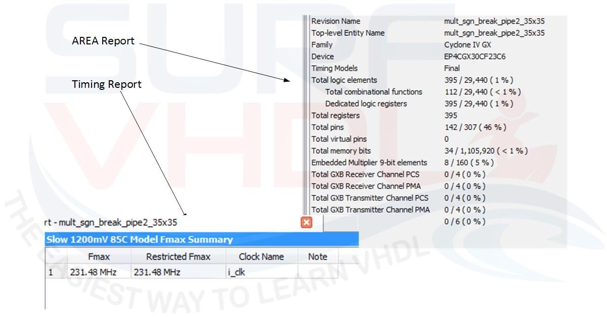
Figure 10 – Area and Timing report of 35×35 pipeline multiplier on Cyclone IV
As clear in this case, the pipeline implementation gives an important speed-up in terms of timing, doubling the performances.
Conclusion & Best Practices
In this post, we considered the VHDL implementation of a multiplier. If we are using an FPGA we should check if the silicon provides the hardware macro for the multiplier. If the multiplier is present in the FPGA as dedicated silicon, we can use them directly using the “*” operator. We must pay attention to the maximum width in bit for the operand, if we use operand with the number of bits is less than or equal to the maximum number provided by the hardware macro the VHDL code will be mapped directly into the hardware multiplier as seen in the previous example. In case we need more bit than the maximum number provided we may need to use a pipeline approach. The examples provided above with the Cyclone IV FPGA, but the same consideration can be extended to the others technologies, show that since the number of bit of the operand is less than or equal to 18, no benefit is present in pipeline implementation as summarized in Figure 11.
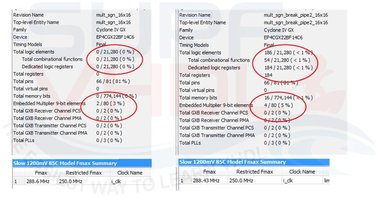
Figure 11 – Multiplier 16×16 comparison normal and pipeline
In the case of multiplier 35×35 the pipeline implementation has a great impact on performances in terms of speed as summarized. In this case, it is clear that despite an increment of register due to the pipeline, the timing performances increment is 2X.
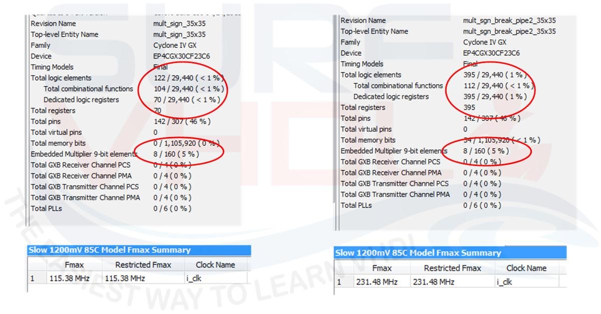
Figure 12 – Multiplier 35×35 comparison normal and pipeline
If you appreciated this post, please help us to share it with your friends.
If you need to contact us, please write to: surf.vhdl@gmail.com