
Control logic implementation
A programmable timeout counter is a common building block in digital design, used to detect when an expected event does not occur within a specified time window. Typical applications include watchdog timers, communication protocol timeouts (e.g., I2C bus stall detection), and sequencing controllers.
In this post, we want to implement a simple exercise in order to show how to implement a programmable time-out counter that uses three different input coding. It is an exercise in control logic that you can use in your FPGA/ASIC design.
The control logic is explained in Figure1:
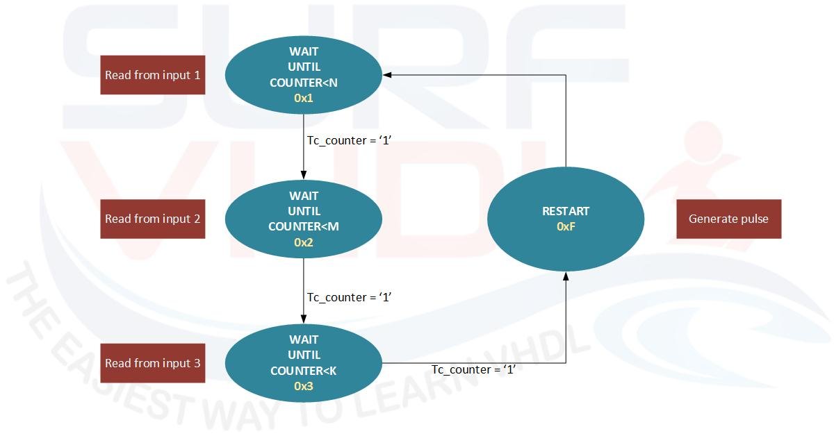
Figure1 – Programmable Time-Out Counter Control logic
we need to count three different types of events and the counting values can be programmed up to three different ways. For instance, starting with count 3 pulses from input 1 then 5 pulses from input 2 and then 7 pulses from input three. After that, the control logic shall generate a pulse.
You can use this example as a template if you need to implement a similar control logic in your design. It can be viewed as a step programmable timeout controller.
VHDL code for time out counter
In the VHDL code implementation of the programmable timeout counter, we are using a different approach for describing the Finite State Machine with respect to the canonical one pointed out in this post.
In this case, the definition of the state of the control logic is implemented using a constant instead of enumeration type provided by VHDL.
Here you can find an example that uses the VHDL enumeration type facility to implement an FSM.
library ieee;
use ieee.std_logic_1164.all;
use ieee.numeric_std.all;

entity programmable_time_out is
port (
  i_clk                : in  std_logic;
  i_rstb               : in  std_logic;
  i_sync_reset         : in  std_logic;
  i_count_module_1     : in  std_logic_vector(7 downto 0);
  i_count_module_2     : in  std_logic_vector(7 downto 0);
  i_count_module_3     : in  std_logic_vector(7 downto 0);
  i_input_1            : in  std_logic;
  i_input_2            : in  std_logic;
  i_input_3            : in  std_logic;
  o_pulse              : out std_logic;
  o_status_counter     : out std_logic_vector(7 downto 0);
  o_status_fsm         : out std_logic_vector(3 downto 0));
end programmable_time_out;

architecture rtl of programmable_time_out is
constant C_NBIT_STATE             : integer := 4;
constant ST_WAIT_UNTIL_COUNT1     : std_logic_vector(C_NBIT_STATE-1 downto 0) := X"1";
constant ST_WAIT_UNTIL_COUNT2     : std_logic_vector(C_NBIT_STATE-1 downto 0) := X"2";
constant ST_WAIT_UNTIL_COUNT3     : std_logic_vector(C_NBIT_STATE-1 downto 0) := X"3";
constant ST_RESET                 : std_logic_vector(C_NBIT_STATE-1 downto 0) := X"F";

signal r_st_present               : std_logic_vector(C_NBIT_STATE-1 downto 0);
signal w_st_next                  : std_logic_vector(C_NBIT_STATE-1 downto 0);

signal r_counter                  : unsigned(7 downto 0);
signal r_counter_module           : unsigned(7 downto 0);
signal r_counter_tc               : std_logic;
signal r_counter_ena              : std_logic;

begin

r_counter_tc  <= '1' when (r_counter >= r_counter_module) else '0';

p_state : process(i_clk,i_rstb)
begin
  if(i_rstb='0') then
    r_st_present            <= ST_RESET;
  elsif(rising_edge(i_clk)) then
    if(i_sync_reset='1') then
      r_st_present            <= ST_RESET;
    else
      r_st_present            <= w_st_next;
    end if;
  end if;
end process p_state;

p_comb : process(
                 r_st_present                       ,
                 r_counter_tc                       ,
                 i_input_2                          ,
                 i_input_3                          )
begin
  case r_st_present is

    when ST_WAIT_UNTIL_COUNT1  =>
      if (r_counter_tc='1') then
        w_st_next  <= ST_WAIT_UNTIL_COUNT2;
      else
        w_st_next  <= ST_WAIT_UNTIL_COUNT1;
      end if;

    when ST_WAIT_UNTIL_COUNT2  =>
      if (r_counter_tc='1') then
        w_st_next  <= ST_WAIT_UNTIL_COUNT3;
      else
        w_st_next  <= ST_WAIT_UNTIL_COUNT2;
      end if;

    when ST_WAIT_UNTIL_COUNT3  =>
      if (r_counter_tc='1') then
        w_st_next  <= ST_RESET;
      else
        w_st_next  <= ST_WAIT_UNTIL_COUNT3;
      end if;

    when others => -- ST_RESET  =>
      w_st_next  <= ST_WAIT_UNTIL_COUNT1;

  end case;
end process p_comb;

p_state_out : process(i_clk,i_rstb)
begin
  if(i_rstb='0') then
    o_pulse           <= '0';
    o_status_counter  <= (others=>'0');
    o_status_fsm      <= ST_RESET;
    r_counter_module  <= (others=>'0');
    r_counter_ena     <= '0';
    r_counter         <= (others=>'0');
  elsif(rising_edge(i_clk)) then
    o_status_counter  <= std_logic_vector(r_counter);
    o_status_fsm      <= r_st_present;
    case r_st_present is
      when ST_WAIT_UNTIL_COUNT1  =>
        o_pulse           <= '0';
        r_counter_module  <= unsigned(i_count_module_1);
        r_counter_ena     <= i_input_1;

        if(r_counter_tc='1') then
          r_counter       <= (others=>'0');
        elsif(r_counter_ena='1') then
          r_counter       <= r_counter + 1;
        end if;

      when ST_WAIT_UNTIL_COUNT2  =>
        o_pulse           <= '0';
        r_counter_module  <= unsigned(i_count_module_2);
        r_counter_ena     <= i_input_2;

        if(r_counter_tc='1') then
          r_counter       <= (others=>'0');
        elsif(r_counter_ena='1') then
          r_counter       <= r_counter + 1;
        end if;

      when ST_WAIT_UNTIL_COUNT3  =>
        o_pulse           <= '0';
        r_counter_module  <= unsigned(i_count_module_3);
        r_counter_ena     <= i_input_3;

        if(r_counter_tc='1') then
          r_counter       <= (others=>'0');
        elsif(r_counter_ena='1') then
          r_counter       <= r_counter + 1;
        end if;

      when others=>  -- ST_RESET  =>
        o_pulse           <= '1';
        r_counter_module  <= unsigned(i_count_module_1);
        r_counter_ena     <= '0';
        r_counter         <= (others=>'0');
    end case;
  end if;
end process p_state_out;

end rtl;
Live FSM Simulator
Click the active input button to increment the counter. The FSM transitions automatically when the target count is reached.
What are the differences from the use of enumeration types?
Regarding the logic behavior there are no main differences.
The enumeration type approach is more readable during VHDL simulation.
Regarding the digital design implementation in FPGA/ASIC this approach allows you to have a better control on the coding of the status of the control logic. In this case, you can code the FSM state as
- one-hot
- binary
- gray code
directly during the definition phase without specifying the encoding type to the synthesis tool. In this case, you can implement a deeper control on FSM implementation.
In the VHDL code of the programmable timeout design, we have reported as the status signal the internal FSM status and internal counter as you can see on Figure2.
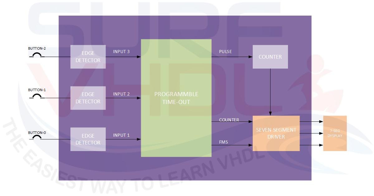
Figure2 – Implementation of Programmable Time Out counter on DE0 board
You can use this info as debug information as will be clear watching the video of the demo on DE0 board.
VHDL code simulation
In the simulation, the test bench is set to have
- input_1 = 4
- input_2 = 3
- input_3 = 5
In actual fact, from the wave windows, it is clear that after 4 input-1 pulses the control logic goes to state 2 and other pulses on input-1 are ignored.
After 3 input-2 pulses, the control logic goes to state 3 and only input 3 is evaluated.
After 5 input-3 pulses, the control logic passes through the reset state and toggles the output
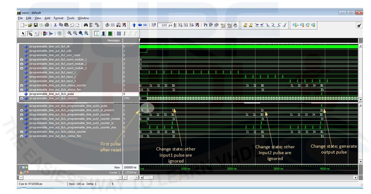
Figure3 – VHDL code simulation of the programmable timeout code
If you appreciated this post, please help us to share it with your friend.
If you need to contact us, please write to: surf.vhdl@gmail.com