
What is a Finite State Machine or FSM?
Which can be an effective and elegant way to describe a control logic? Which strategies would you use?
One possibility is trivial: start writing your control logic with a series of “if-then-else” or “case” statements.
It is definitely not an elegant method, but in some ways it could be efficient if you are particularly skilled at simplifying the description of your control logic.
Another possibility is to use a Finite State Machine (FSM).
A finite state machine is simply a method that allows you to implement a control logic in a simple and efficient way.
Different types of Finite State Machine
There are two different main types of finite state machines the Mealy FSM and the Moore FSM.
The fundamental difference between these two types lies in the management of the outputs:
- The output of the Mealy FSM depends on the present state and inputs.
- The output of a Moore FSM depends only on the present state and not on the inputs.
Figure 1 shows the Mealy FSM.
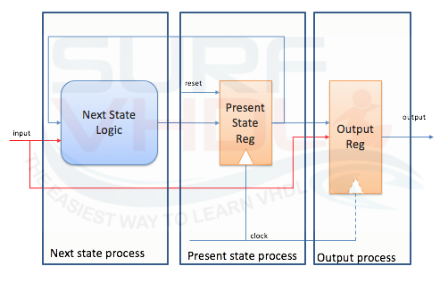
Figure 1 – Mealy FSM schematic view
Figure 2 schematizes the Moore FSM.
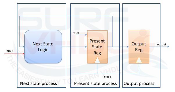
Figure 2 – Moore FSM schematic view
The Moore FSM is preferable to the Mealy FSM since the output of the Moore FSM depends only on the current machine state. No assumptions or checks on the inputs have to be performed to generate the output of the FSM, so the output decoding is simpler to handle.
Moreover, if the output is combinatorial, i.e. not registered, the Moore FSM is safer with respect to Mealy FSM: the long combinatorial path between input and output can generate glitch on the machine output or can reduce dramatically the design timing performances.
Figure 3 shows a visual representation of a simple Moore Finite State Machine;
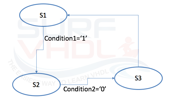
Figure 3 – Visual Representation of FSM
The circles represent the states. The transition from one state to another state is represented by the connection arrows. In order to move from a current state to the next one the condition on the connection arrow shall be verified. If no condition is present on the connection arrow the next state will be the current state after a clock cycle.
In order to visualize the FSM output, a rectangle containing the FSM output can be added to the diagram as in Figure 4
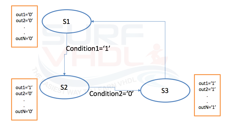
Figure 4 – Visual Representation of FSM with output state
How to write the VHDL code for Moore FSM
If you represent your FSM with a diagram like the one presented in Figure 3 or Figure 4, the VHDL FSM coding is straightforward and can be implemented as a VHDL template. We can use three processes as in Figure 2 :
- Clocked Process for driving the present state;
- Combinatorial Process for the next state decoding starting from the present state and the inputs;
- Clocked or combinatorial Process driving the FSM output.
The FSM can also be encoded with a single process, but the FSM VHDL template proposed is used to make the code more linear and readable. For example, you can find the similar template in the Vivado Synthesis user guide (UG901).
Note that the present state is stored in registers while the next state is completely combinatorial.
library ieee;
use ieee.std_logic_1164.all;
use ieee.numeric_std.all;

entity control_logic is
 port (
  i_clk       : in  std_logic;
  i_rstb      : in  std_logic;
  -- input
  i_input1    : in  std_logic;
  i_input2    : in  std_logic;
  -- output
  o_output1   : out std_logic;
  o_output2   : out std_logic;
  o_output3   : out std_logic);
end control_logic;

architecture rtl of control_logic is

type t_control_logic_fsm is (
                          ST_S1      ,
                          ST_S2      ,
                          ST_S3      );


signal r_st_present    : t_control_logic_fsm;
signal w_st_next       : t_control_logic_fsm;

begin
--------------------------------------------------------------------
-- FSM
p_state : process(i_clk,i_rstb)
begin
  if(i_rstb='0') then
    r_st_present            <= ST_S3;
  elsif(rising_edge(i_clk)) then
    r_st_present            <= w_st_next;
  end if;
end process p_state;

p_comb : process(
                 r_st_present    ,
                 i_input1        ,
                 i_input2        )
begin
  case r_st_present is
    when ST_S1 =>
      if (i_input1='1') then
        w_st_next  <= ST_S2;
      else
        w_st_next  <= ST_S1;
      end if;
    when ST_S2 =>
      if (i_input1='0') and (i_input2='1')then
        w_st_next  <= ST_S3;
      else
        w_st_next  <= ST_S2;
      end if;
    when others=> -- ST_S3 =>
      w_st_next  <= ST_S1;

  end case;
end process p_comb;

p_state_out : process(i_clk,i_rstb)
begin
  if(i_rstb='0') then
    o_output1     <= '0';
    o_output2     <= '0';
    o_output3     <= '0';

  elsif(rising_edge(i_clk)) then

    case r_st_present is
      when ST_S1        =>
        o_output1     <= '1';
        o_output2     <= '0';
        o_output3     <= '0';
      when ST_S2        =>
        o_output1     <= '0';
        o_output2     <= '1';
        o_output3     <= '0';
      when others => -- ST_S3 =>
        o_output1     <= '0';
        o_output2     <= '0';
        o_output3     <= '1';
    end case;
  end if;
end process p_state_out;

end rtl;
The outputs can be registered or not. The advice is to register all the FSM outputs unless it is absolutely necessary to recover a clock cycle, I mean you have to provide the FSM output with the lowest possible clock latency. Using registered outputs, you will improve the system timing performances.
Example Finite State Machine in VHDL
Ok at this point you must be wondering,
Would it not be better to make an example so that I really understand this whole theory about the FSM?
Ok, you’re right.
A good example is far better than a good precept.
Suppose we want to implement an automatic vending machine.
The machine can accept only one-dollar or five-dollar bills.
The vending machine can provide two different types of product:
- product P1, cost 1 dollar
- product P2, cost 3 dollars
The machine must be able to:
- select the type of product
- decode a number of bills inserted
- provide the product if the money is sufficient otherwise wait until the correct amount.
At any moment it shall be possible to have a refund in the case the user no longer wishes to take the product.
In this example, we describe a possible implementation of the architecture of the vending machine and then we will see how to implement the control logic in VHDL using a Finite State Machine (FSM).
In Figure 5 is reported a possible architecture:
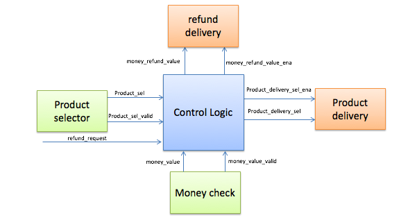
Figure 5 – An example of Vending Machine Architecture
- The product selector block is aimed to provide the current product selection.
- The money check block provides the current amount of money inserted into the machine
- The product delivery block provides the product selected in case of the amount of money inserted is enough to take the product
- The refund delivery block gives back all the money in case of refund request or gives back the refund if required
Figure 6 shows a possible implementation of the FSM, in the control logic block:
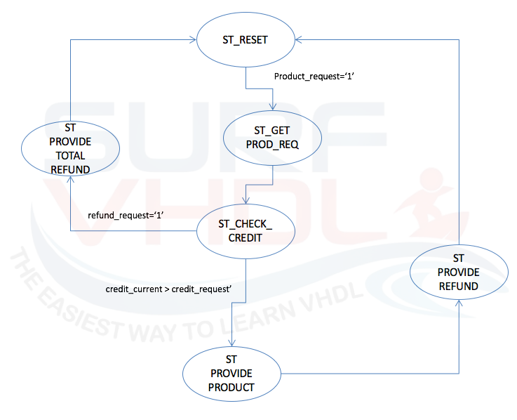
Figure 6 – Vending Machine Control Logic possible implementation
In the state ST_RESET, the FSM waits for product selection.
When the product is selected, the FSM changes its state and goes in the state ST_GET_PROD_REQ. Here the product selected is latched into the vending machine control logic. After one clock cycle (no condition is present on the connection arrow), the State Machine goes to the state ST_CHECK_CREDIT until the credit is greater than or equal to the credit required for the delivery of the currently selected product. In the state ST_CHECK_CREDIT, if a refund is requested, the FSM changes its state to ST_PROVIDE_TOTAL_REFUND and enables the total refund delivery, then goes to ST_RESET. Otherwise, if the credit is sufficient for product delivery, the ST_PROVIDE_PRODUCT enables the delivery of the selected product. After product delivery, the state ST_PROVIDE_REFUND makes the vending machine provide the refund if the credit inserted were greater than the credit requested.
FSM Inputs
Set your inputs, then click the Clock Pulse button to simulate a rising edge in VHDL. Outputs are registered, so you need a clock tick to process them!
library ieee;
use ieee.std_logic_1164.all;
use ieee.numeric_std.all;

entity control_logic is
 port (
  i_clk                       : in  std_logic;
  i_rstb                      : in  std_logic;
  i_refund_request            : in  std_logic;  -- 1 clock pulse
  -- from product selector
  i_product_sel               : in  std_logic;  -- '0'=> product 1, '1'=> product 2
  i_product_sel_valid         : in  std_logic;  -- 1 clock pulse
  -- from money check
  i_money_value               : in  std_logic;  -- '0' => 1 dollar; '1' => five dollars
  i_money_value_valid         : in  std_logic;  -- 1 clock pulse
  -- to product delivery
  o_product_delivery_sel      : out std_logic;  -- '0'=> product 1, '1'=> product 2
  o_product_delivery_sel_ena  : out std_logic;  -- 1 clock pulse
  -- to delivery refund
  o_money_refund_value        : out std_logic_vector(3 downto 0); -- refund value, up to 15 dollars = (2^4)-1
  o_money_refund_value_ena    : out std_logic);  -- 1 clock pulse
end control_logic;

architecture rtl of control_logic is

constant C_PRICE_PRODUCT_1       : integer := 1;
constant C_PRICE_PRODUCT_2       : integer := 3;

type t_money_table is array(0 to 1) of integer range 1 to 5;
constant money_table : t_money_table := (1, 5);

type t_control_logic_fsm is (
                          ST_RESET                ,
                          ST_ST_GET_PROD_REQ      ,
                          ST_CHECK_CREDIT         ,
                          ST_PROVIDE_PRODUCT      ,
                          ST_PROVIDE_TOTAL_REFUND ,
                          ST_PROVIDE_REFUND       );


signal r_price_product             : integer range 1 to 3;
signal r_price_product_counter     : integer range 0 to 15;
signal r_refund                    : integer range 0 to 15;
signal w_money_value               : integer range 1 to 15;

signal r_st_present                : t_control_logic_fsm;
signal w_st_next                   : t_control_logic_fsm;

begin

-- convert input money selector to current money value
w_money_value <= money_table(0) when (i_money_value='0') else money_table(1);

--------------------------------------------------------------------
-- FSM
p_state : process(i_clk,i_rstb)
begin
  if(i_rstb='0') then
    r_st_present            <= ST_RESET;
  elsif(rising_edge(i_clk)) then
    r_st_present            <= w_st_next;
  end if;
end process p_state;

p_comb : process(
                 r_st_present                       ,
                 i_product_sel_valid                ,
                 i_refund_request                   ,
                 r_price_product_counter            ,
                 r_price_product
                 )
begin
  case r_st_present is
    when ST_ST_GET_PROD_REQ  =>
      w_st_next  <= ST_CHECK_CREDIT;

    when ST_CHECK_CREDIT     =>
      if (r_price_product_counter>=r_price_product) then
        w_st_next  <= ST_PROVIDE_PRODUCT;
      elsif(i_refund_request='1') then
        w_st_next  <= ST_PROVIDE_TOTAL_REFUND;
      else
        w_st_next  <= ST_CHECK_CREDIT;
      end if;

    when ST_PROVIDE_PRODUCT  =>
      w_st_next  <= ST_PROVIDE_REFUND;

    when ST_PROVIDE_REFUND   =>
      w_st_next  <= ST_RESET;

    when ST_PROVIDE_TOTAL_REFUND   =>
      w_st_next  <= ST_RESET;

    when others=> -- ST_RESET            =>
      if (i_product_sel_valid='1') then
        w_st_next  <= ST_ST_GET_PROD_REQ;
      else
        w_st_next  <= ST_RESET;
      end if;

  end case;
end process p_comb;

p_state_out : process(i_clk,i_rstb)
begin
  if(i_rstb='0') then
    r_price_product            <= C_PRICE_PRODUCT_1;
    r_price_product_counter    <= 0;
    r_refund                   <= 0;
    o_money_refund_value_ena   <= '0';
    o_product_delivery_sel     <= '0';
    o_product_delivery_sel_ena <= '0';

  elsif(rising_edge(i_clk)) then

    case r_st_present is
      when ST_ST_GET_PROD_REQ        =>
        if(i_product_sel='0') then
          r_price_product            <= C_PRICE_PRODUCT_1;
        else
          r_price_product            <= C_PRICE_PRODUCT_2;
        end if;
        o_money_refund_value_ena   <= '0';
        o_product_delivery_sel     <= i_product_sel;
        o_product_delivery_sel_ena <= '0';

      when ST_CHECK_CREDIT           =>
        if(i_money_value_valid='1') then
          r_price_product_counter   <= r_price_product_counter + w_money_value;
        end if;

      when ST_PROVIDE_PRODUCT        =>
        o_product_delivery_sel_ena <= '1';
        o_money_refund_value_ena   <= '0';

      when ST_PROVIDE_REFUND         =>
        r_refund                   <= r_price_product_counter - r_price_product;
        o_product_delivery_sel_ena <= '0';
        o_money_refund_value_ena   <= '1';

      when ST_PROVIDE_TOTAL_REFUND   =>
        r_refund                   <= r_price_product_counter;
        o_product_delivery_sel_ena <= '0';
        o_money_refund_value_ena   <= '1';

      when others =>  -- ST_RESET            =>
        r_price_product_counter    <= 0;
        r_refund                   <= 0;
        o_product_delivery_sel_ena <= '0';
        o_money_refund_value_ena   <= '0';
    end case;
  end if;
end process p_state_out;

o_money_refund_value      <= std_logic_vector(to_unsigned(r_refund,4));

end rtl;
VHDL Code Example of the Control Logic of a Vending Machine
Now it should be clear how to implement a Moore FSM in VHDL. Using the FSM VHDL code template provided above, you will implement a Finite State Machine in its canonical implementation.
Moreover, you should be able to implement your own Vending Machine in VHDL!
If you appreciated this post, please help us share it with your friends.
If you need to contact us, please write to surf.vhdl@gmail.com