Classical Method
As you know, the classical method to measure a pulse characteristic is to use an oscilloscope. The oscilloscope can measure amplitude, width, frequency and many other pulse characteristics as in Figure1. Many times we do not have an oscilloscope or we don’t have the possibility to reach the signal we want to measure.
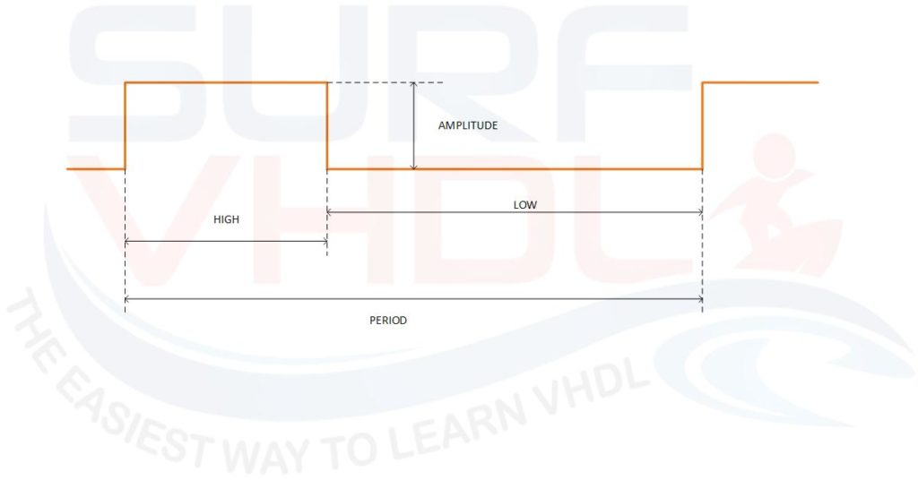
For example, if you want to measure a pulse inside your FPGA, it could be difficult. In this case, you don’t need to know the amplitude of the pulse: it is a digital signal that can get the values ‘0’ or ‘1’.
The amplitude depends on of the technology that is you using and it is guaranteed by the FPGA vendors. For instances, the modern FPGAs core work at 0.9 V. As you can imagine, the high and low level of a pulse will be different from which you can probe on FPGA pin. Anyway, you can output the signal and use a scope but if you need to measure the pulse on an equipment inside a rack it could be a problem.
Measure the pulse length with FPGA
Remember you have an FPGA, Field Programmable Gate Array, you can use few part of its logic gate in order to implement a simple circuit that can give you the measurement you need of the pulse.
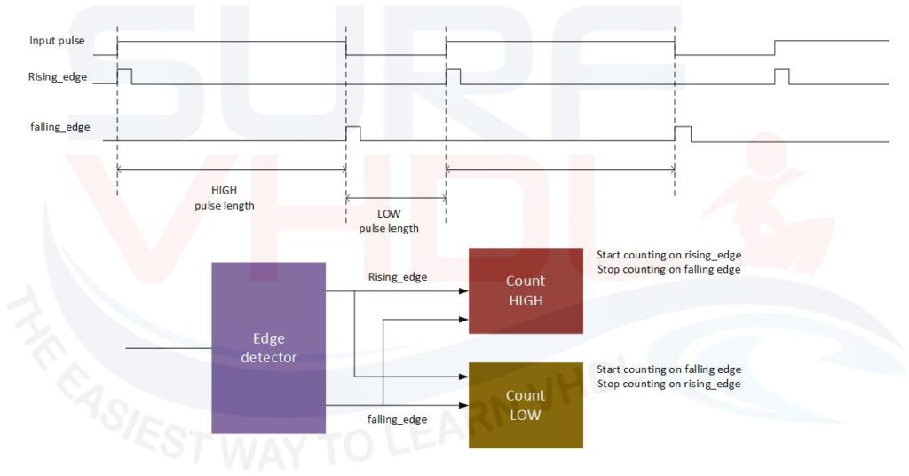
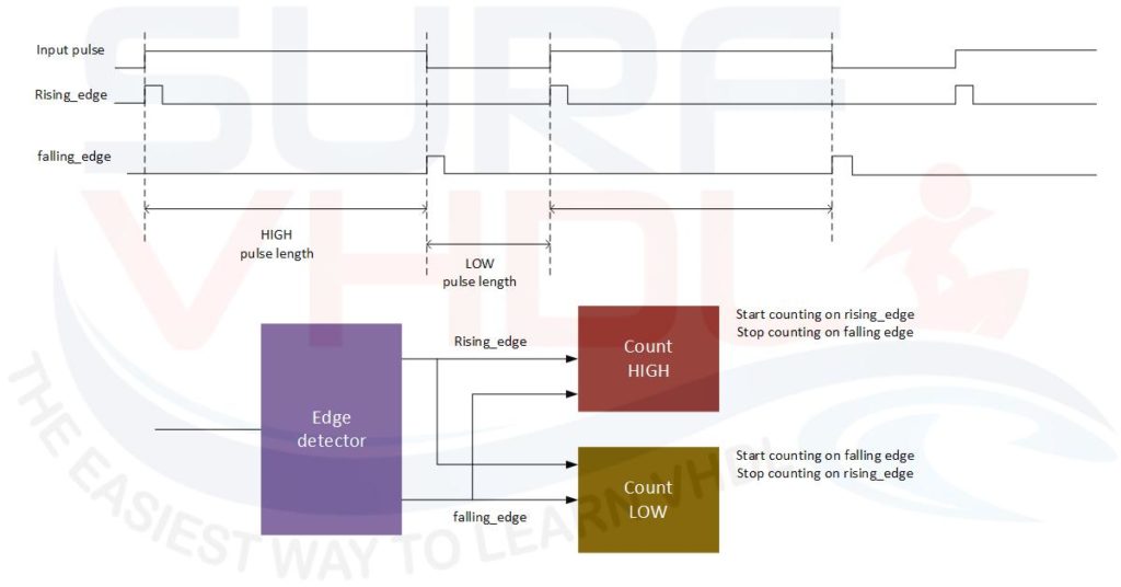
In pulse measurement, we need to detect the rising and falling edge of the pulse itself. Figure2 shows how to measure the HIGH and LOW level of the pulse:
- HIGH phase measurement is between rising and falling edge
- LOW phase measurement is between falling and rising edge
As you can see it is very simple to implement a design able to compute the measurement:
- edge detector
- a counter for HIGH phase
- a counter for LOW phase
- simple control logic
The HIGH phase counter will start on rising edge and stop counting on falling edge
The LOW phase counter will start on falling edge and stop counting on rising edge
Click Here to enroll the free course
“Measure Pulse Duration in FPGA Using VHDL”
VHDL Code for pulse length counter
A possible VHDL implementation of a pulse length counter is reported here below:
library ieee;
use ieee.std_logic_1164.all;
use ieee.numeric_std.all;

entity pulse_len_measure is
generic (
  N                           : integer:=8);
port (
  i_clk                       : in  std_logic;
  i_rstb                      : in  std_logic;
  i_input                     : in  std_logic;
  o_pulse_len_hi              : out std_logic_vector(N-1 downto 0);
  o_pulse_len_lo              : out std_logic_vector(N-1 downto 0));
end pulse_len_measure;

architecture rtl of pulse_len_measure is
constant C_MAX_COUNT           : unsigned(N-1 downto 0):=(others=>'1');
signal r_count_hi_ena          : std_logic;
signal r_count_hi              : unsigned(N-1 downto 0);
signal r_count_lo              : unsigned(N-1 downto 0);
signal r_count_lo_ena          : std_logic;
signal r_rise                  : std_logic;
signal r_fall                  : std_logic;
signal p_input                 : std_logic_vector(0 to 2); -- input pipe

begin

p_edge_detector : process(i_clk,i_rstb)
begin
  if(i_rstb='0') then
    r_rise       <= '0';
    r_fall       <= '0';
    p_input      <= (others=>'0');
  elsif(rising_edge(i_clk)) then
    r_rise       <= not p_input(2) and p_input(1);
    r_fall       <= not p_input(1) and p_input(2);
    p_input      <= i_input&p_input(0 to p_input'length-2);
  end if;
end process p_edge_detector;

p_count_hi : process(i_clk,i_rstb)
begin
  if(i_rstb='0') then
    r_count_hi_ena  <= '0';
    r_count_hi      <= to_unsigned(1,N);
    o_pulse_len_hi  <= (others=>'0');
  elsif(rising_edge(i_clk)) then
    if(r_rise='1') then
      r_count_hi_ena  <= '1';
    elsif(r_fall='1') then
      r_count_hi_ena  <= '0';
      o_pulse_len_hi  <= std_logic_vector(r_count_hi);
    end if;

    if(r_count_hi_ena='1') then
      if(r_count_hi<C_MAX_COUNT)then
        r_count_hi      <= r_count_hi + 1;
      end if;
    else
      r_count_hi      <= to_unsigned(1,N);
    end if;
  end if;
end process p_count_hi;

p_count_lo : process(i_clk,i_rstb)
begin
  if(i_rstb='0') then
    r_count_lo_ena  <= '0';
    r_count_lo      <= to_unsigned(1,N);
    o_pulse_len_lo  <= (others=>'0');
  elsif(rising_edge(i_clk)) then
    if(r_fall='1') then
      r_count_lo_ena  <= '1';
    elsif(r_rise='1') then
      r_count_lo_ena  <= '0';
      o_pulse_len_lo  <= std_logic_vector(r_count_lo);
    end if;

    if(r_count_lo_ena='1') then
      if(r_count_lo<C_MAX_COUNT) then
        r_count_lo      <= r_count_lo + 1;
      end if;
    else
      r_count_lo      <= to_unsigned(1,N);
    end if;
  end if;
end process p_count_lo;

end rtl;
Pulse length counters VHDL Code simulation
In the VHDL code, we introduced a saturation in length counting. This implementation avoids the counter wrapping, so in case you should read the maximum value on one of the two counters you can guess that the length computed has saturated the counter capability.
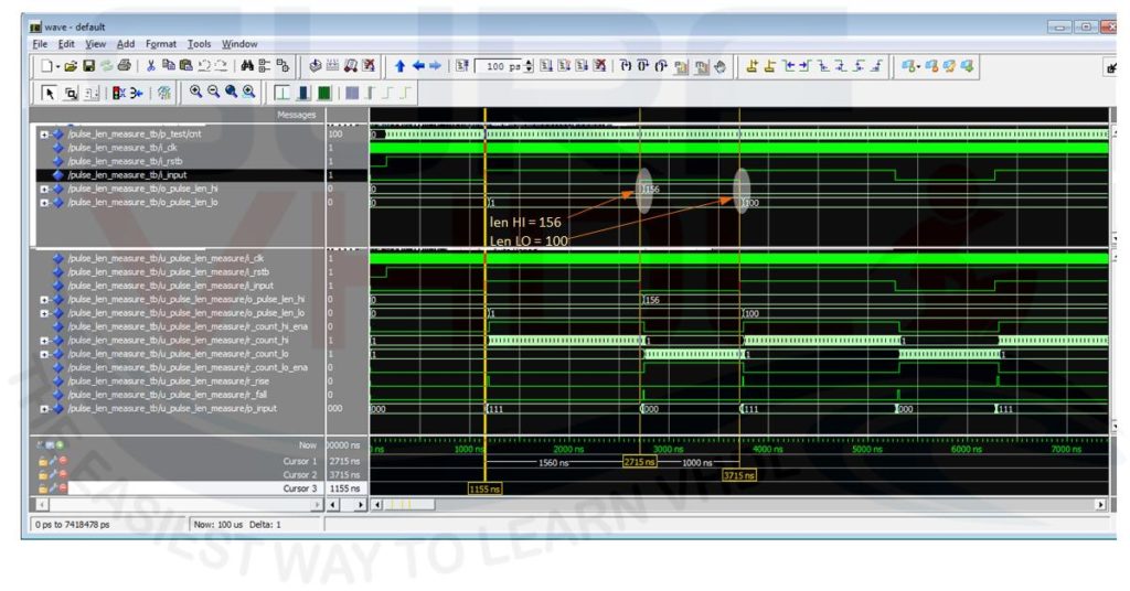
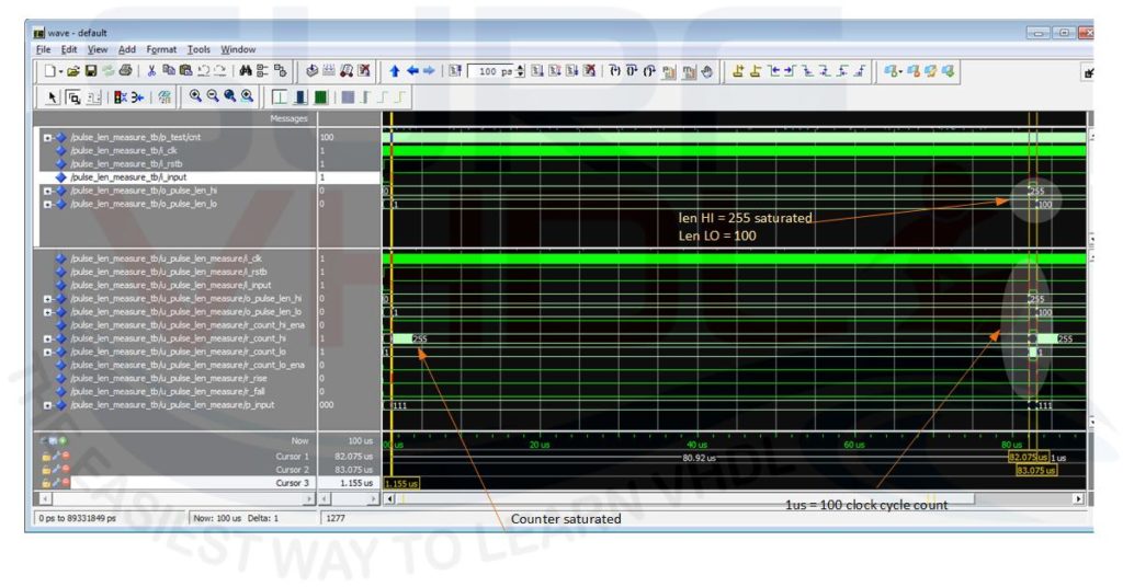
In the simulation, we simulated the two condition where the counter is not saturated in Figure3 and when the HIGH pulse is higher than the counter capability in Figure4
Click Here to enroll the free course
“Measure Pulse Duration in FPGA Using VHDL”
Video for pulse length counter
In the video, you can see an implementation on DE0 Altera board of the pulse length counter.
In order to demonstrate how the counters work we are using the 7-segment provided by the DE0 board in order to output the counting value. The pulses are generated using the push button on the board so, as you can understand, the pulse length values HIGH and LOW are “human generated” and will be in the order of seconds.
In this case to measure the length using only 8 bit of the 7-segment display we need to slow down the clock of the pulse counter, as you can watch the video.
[video_player type=”youtube” youtube_remove_logo=”Y” width=”560″ height=”315″ align=”center” margin_top=”0″ margin_bottom=”20″]aHR0cHM6Ly95b3V0dS5iZS9CcHZUV2h4ZHNmYw==[/video_player]
If you appreciated this post, please help us to share it with your friend.
[social_sharing style=”style-7″ fb_like_url=”https://surf-vhdl.com/how-to-measure-pulse-duration-using-vhdl” fb_color=”light” fb_lang=”en_US” fb_text=”like” fb_button_text=”Share” tw_lang=”en” tw_url=”https://surf-vhdl.com/how-to-measure-pulse-duration-using-vhdl” tw_button_text=”Share” g_url=”https://surf-vhdl.com/how-to-measure-pulse-duration-using-vhdl” g_lang=”en-GB” g_button_text=”Share” linkedin_url=”https://surf-vhdl.com/how-to-measure-pulse-duration-using-vhdl” linkedin_lang=”en_US” alignment=”center”]
If you need to contact us, please write to: surf.vhdl@gmail.com
We appreciate any of your comment, please post below:
how to generate the continuous pulse for the “abcd”,”edf1″,”gab1″ ……….
what do you mean?
i try to use the code for a nexys4 board but it doesn’t works
what goes wrong?
i tried thise code inside a nexys 4 but it does n t work
what is the problem?
I try to use it for nexys 3 but nothing appears in the ISIM window everything is in U
what is your problem?
Hello, my question is similar but a very different case! In my application, I need to measure the frequency and amplitude of an incoming sinusoidal signal (analog). And this has to be done in VHDL (not synthesisable, because this isn’t on FPGA but outside). Is it possible to do? If yes, then please could you help me with this?
Thanks in advance.
If you don’t need to synthesise the code, you can use VHDL like a programming language.
In this case you can find a lot of algorithm in literature
It was really great … although I still do not understand what you mean by p_input! What does it do in the circuit? Why did you define it as 3 bits? What happened in lines 35, 36 and 37 ?! Thank you for your reply
p_input is a pipeline, a shift register is used to delay the input signal “i_input”.
It is a simple trick the generate the delayed version of the signal, in this case 3 registers (0 to 2) and derive the rising and falling edge
Sir,
Could you please give the logic in verilog..