
What is Pulse Width Modulation (PWM)?
Pulse width modulation (PWM) is a digital technique used for controlling an analog circuit. A PWM controller can be implemented either using a microcontroller or FPGA digital outputs.
The PWM is employed in many applications, ranging from measurement and communications to power control and conversion.
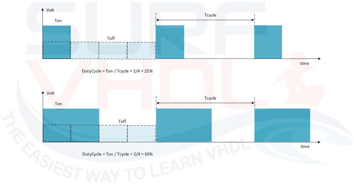
Figure 1 – PWM typical waveform
How PWM Controls Analog Circuits
Let’s imagine we want to dim the intensity of a lamp. A first simple possibility is to implement a voltage divider using a variable resistor, as shown in Figure 2. By doing this, the light intensity varies proportionally to the voltage present on the lamp pin by varying the resistor R2.
In this approach, the voltage on the lamp VL is the division of Vs across R1 and RLT, where RLT is the total resistance given by the parallel of R2 and RL. This approach is not efficient in terms of power consumption; in fact, when we want to use maximum power on the lamp, R2 is set to have high impedance (i.e., it can be considered open), and all the current flows through R1 and the lamp. When the lamp light is attenuated, the R2 value is low (i.e., a few ohms). This means that the current flows through both R1 and R2.
Using this approach, when we need light attenuation, R1 and R2 must be able to dissipate all the power not used by the lamp. As you can understand, this is not an optimal approach!
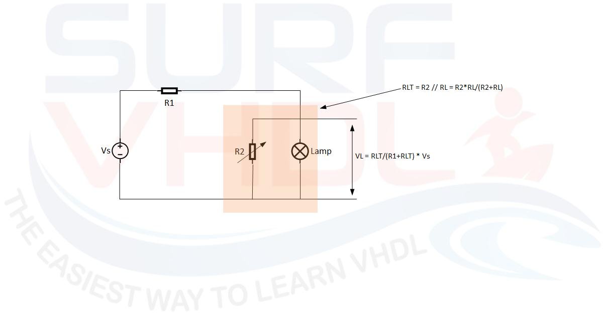
Figure 2 – Lamp dimmer using variable resistor
A more efficient approach is the following. Imagine being able to turn your lamp on and off very fast. In this case, you can modulate the light simply by modifying the duty cycle of your switch. If you need maximum light, leave the switch always on; if you want to attenuate the light, vary the duty cycle proportionally.
The average voltage on the lamp pin is the average voltage in the PWM period:
VL = (Vs x Ton) / Tp = Vs x DutyCycle
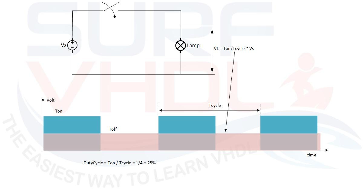
Figure 3 – Dimmer a lamp using digital control like PWM
Of course, when the switch is off, no current flows in your circuit, and no power is wasted! This is a very simple method for using PWM to control a lamp. You can use the same approach to control a motor.
Main Parameters of a PWM Waveform
Let’s see what the main parameters are to define the PWM waveform shown in Figure 1:
- PWM Period: the time between two consecutive ON periods
- Duty Cycle: the ratio of the ON-time to the period
- PWM Frequency: the inverse of the period
How to implement a PWM in VHDL
Get the complete VHDL code from this article.
VHDL Architecture for a Programmable PWM
In order to implement a PWM in VHDL, we need a simple counter, as shown in Figure 4.
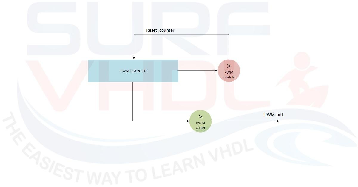
Figure 4 – Example of hardware PWM architecture
The PWM period is defined as the number of clock cycles we want the counter to count before restarting. When the counter value is less than the PWM-width value, the PWM output is HIGH; otherwise, it is LOW.
Resolution vs. PWM Frequency Trade-off
The generic parameter N sets the maximum number of bits for the PWM counter. The input signal i_pwm_module determines the actual terminal count. The PWM frequency is given by:
Fpwm = Fclk / (i_pwm_module + 1)
As you can see from the formula, there is a direct trade-off. If you need a higher duty-cycle resolution (a larger i_pwm_module), your PWM frequency drops, assuming the system clock Fclk remains fixed.
Glitch-Free Duty Cycle Update
Notice the w_tc_pwm_counter signal in the architecture. We use this terminal count flag to strobe the new i_pwm_width value only when the current PWM period is over. Synchronizing the duty cycle update at the end of the period is a standard practice to prevent unwanted glitches or truncated pulses on the output.
PWM VHDL Code Example
Here is the VHDL code implementing the PWM logic:
library ieee;
use ieee.std_logic_1164.all;
use ieee.numeric_std.all;

entity pwm_prog is
generic(
  N : integer := 8); -- number of bit of PWM counter
port (
  i_clk : in std_logic;
  i_rstb : in std_logic;
  i_sync_reset : in std_logic;
  i_pwm_module : in std_logic_vector(N-1 downto 0); -- PWM Freq = clock freq/ (i_pwm_module+1); max value = 2^N-1
  i_pwm_width : in std_logic_vector(N-1 downto 0); -- PWM width = (others=>0)=> OFF; i_pwm_module => MAX ON
  o_pwm : out std_logic);
end pwm_prog;

architecture rtl of pwm_prog is
  signal r_max_count : unsigned(N-1 downto 0);
  signal r_pwm_counter : unsigned(N-1 downto 0);
  signal r_pwm_width : unsigned(N-1 downto 0);
  signal w_tc_pwm_counter : std_logic;
begin

  w_tc_pwm_counter <= '0' when(r_pwm_counter<r_max_count) else '1'; -- use to strobe new word

--------------------------------------------------------------------
p_state_out : process(i_clk,i_rstb)
begin
  if(i_rstb='0') then
    r_max_count <= (others=>'0');
    r_pwm_width <= (others=>'0');
    r_pwm_counter <= (others=>'0');
    o_pwm <= '0';
  elsif(rising_edge(i_clk)) then
    r_max_count <= unsigned(i_pwm_module);

    if(i_sync_reset='1') then
      r_pwm_width <= unsigned(i_pwm_width);
      r_pwm_counter <= to_unsigned(0,N);
      o_pwm <= '0';
    else
      if(r_pwm_counter=0) and (r_pwm_width/=r_max_count) then
        o_pwm <= '0';
      elsif(r_pwm_counter<=r_pwm_width) then
        o_pwm <= '1';
      else
        o_pwm <= '0';
      end if;

      if(w_tc_pwm_counter='1') then
        r_pwm_width <= unsigned(i_pwm_width);
      end if;

      if(r_pwm_counter=r_max_count) then
        r_pwm_counter <= to_unsigned(0,N);
      else
        r_pwm_counter <= r_pwm_counter + 1;
      end if;
    end if;
  end if;
end process p_state_out;

end rtl;
PWM HIGH/LOW Time Parameters
When i_pwm_width is:
- Zero => PWM output is always LOW
- i_pwm_module => PWM output is always HIGH
- K => PWM is K clock cycles HIGH and (i_pwm_module – K) LOW
Interactive PWM Visualizer
Use the interactive widget below to see how i_pwm_module and i_pwm_width affect the duty cycle and output waveform in real time.
VHDL Simulation Results
Figure 5 shows the PWM VHDL code simulation where the PWM counter bit size is set to 8, the PWM period is 256 clock cycles, and the PWM width is set to 10. In the simulation, the clock period is 10 ns.
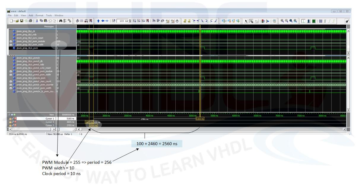
Figure 5 – simulation of VHDL PWM code
RTL Layout Results
To get feedback on the PWM implementation on an FPGA, Figure 6 shows the RTL viewer results for the VHDL code above. The example is relative to an Altera Cyclone II FPGA.
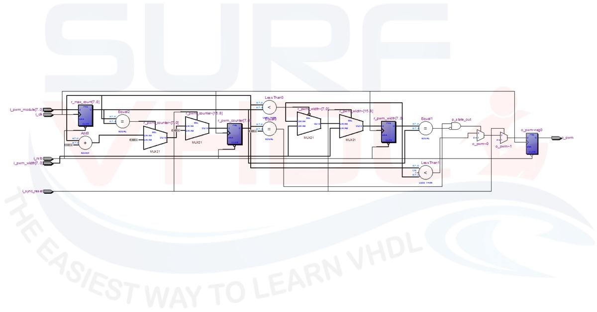
Figure 6 – PWM layout example, RTL viewer
Hardware Implementation on Altera DE0 FPGA
In this video, you can learn how to implement the VHDL code of the PWM described above on a DE0 Altera board. The code is tested using the DE0 board LED: by varying the PWM duty cycle, the light intensity varies accordingly.
Conclusion
Implementing a PWM in VHDL requires a simple counter and a comparator. By managing the terminal count (i_pwm_module) and the high-time threshold (i_pwm_width), you can easily control analog devices like LEDs or motors from your FPGA. Remember to synchronize the duty cycle update to avoid output glitches.
If you appreciated this post, please help us to share it with your friends.
If you need to contact us, please write to: surf.vhdl@gmail.com