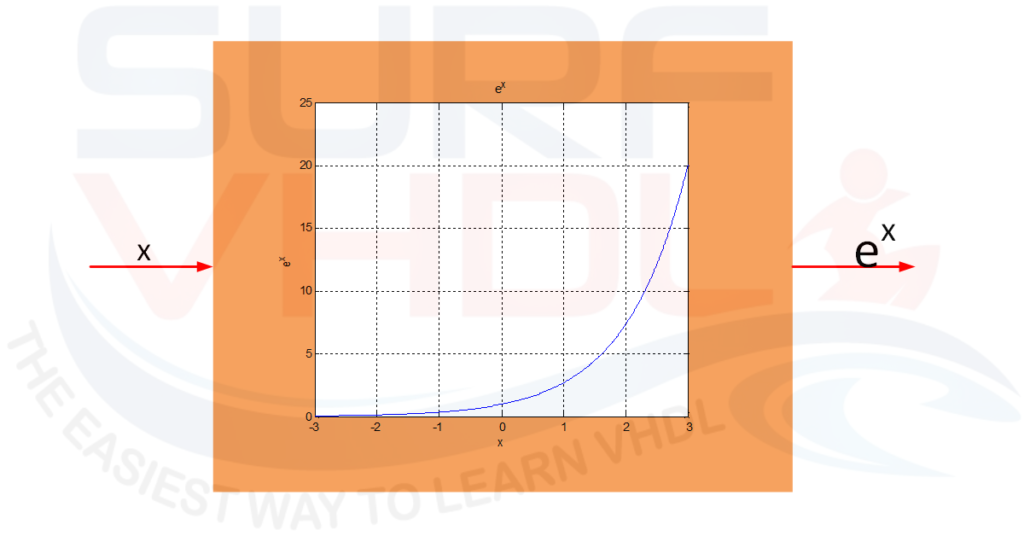
Where the exponential functions are used?
The exponential functions are used mainly where non-linear behavior are present. An example of exp(x) is given in Figure 1. Since we are dealing with an exponential behavior, in the normal use of the function, the value of the exponent is range limited. For example, your algorithm could use 0<x<1, or -1<x<1 and so on. It is very unlikely you should deal with x in the entire real range when you implement a signal processing algorithm in FPGA.
Fixed point implementation
In literature, there are many solutions to implement the exponential function. A possible solution is, for example, the expansion as Taylor series. The implementation as you can understand could be very demanding in terms of operation.
As stated before, in the common use the exp(x) function is used with the argument “x” in a well-defined range. In this case, the implementation can be simplified.
The first thing we should do is to identify the range of the argument and then quantize the argument and the function using a finite number of bit NQA for the argument and NQF for the function output. For example:
-1<= x < 1;
NQA = 4;
NQF = 8;
we are going to use 4 bit for the argument and 8 bit for the exponential function representation. The input “x” is represented with the number -8/8.. +7/8, i.e. 2^4 = 16 interval.
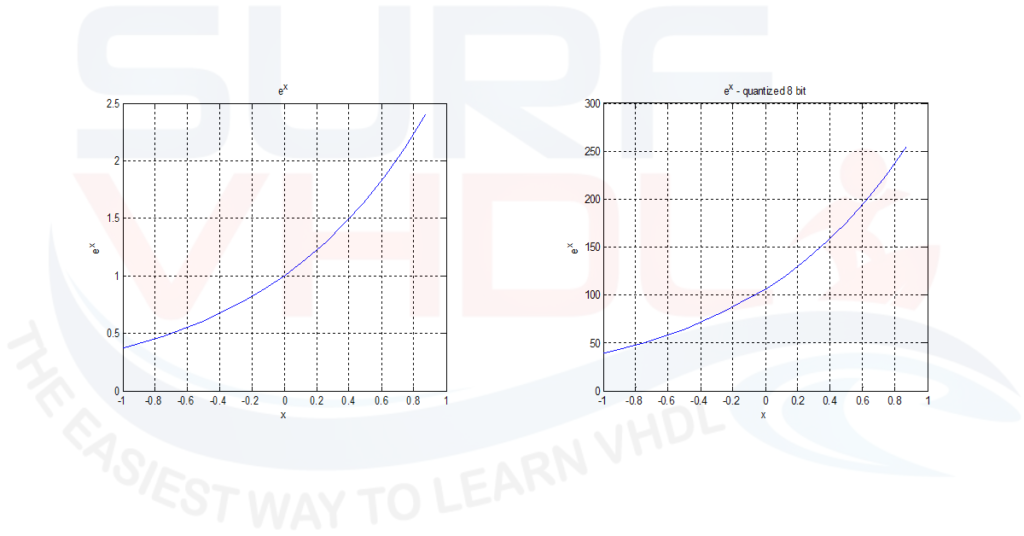
In Figure 2 is reported the exponential function exp(x) for x in the range [-1..1) floating point and 8-bit quantized.
The fixed-point representation can be generated with the following Matlab code:
clear all;
close all;
clc;

NQA = 8;
NQF = 10;

x = [-(2^NQA):1:(2^NQA-1)]'/(2^NQA);  % 256+256 point interval
y = exp(x);

yQ = round(y/max(y)* (2^NQF-1)) ;

plot(x,y)
title('e^x')
ylabel('e^x')
xlabel('x')
grid

figure
plot(x,yQ)
title('e^x - quantized 8 bit')
ylabel('e^x')
xlabel('x')
grid
Matlab code for exp(x) quantization
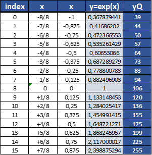
The argument is quantized using 4 bit: the input range step is 1/8. The exponential function is quantized using 8 bit. The quantization is performed normalizing the function to its maximum value and then multiplying by 2^NQF-1 (i.e. 256)
As clear, the quantized value of exp(0) is 106, since exp(0) = 1.
Implementation of exponential function in FPGA using VHDL
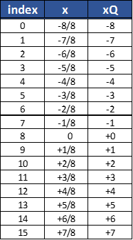
In the previous section, we saw how to perform a fixed point representation of the exp(x) function for x=[-1..1). As clear the fixed point output is in the range [39..255]. The function values can be represented using a table of 16 entry [0..15] as in Figure 3. In the FPGA, the input x can be represented as a 2’complement representation as assumed in Figure 3. The table can be addressed directly with x simply adding 2^(NQA-1) to x, 2^3=8 in the example as reported in Figure 4
library IEEE;
use IEEE.std_logic_1164.all;
use IEEE.numeric_std.all;

entity exp_lut is
port(
  i_clk          : in  std_logic;
  i_rstb         : in  std_logic;
  i_x            : in  std_logic_vector( 3 downto 0);
  o_exp          : out std_logic_vector( 7 downto 0));
end exp_lut;

architecture rtl of exp_lut is
constant C_LUT_DEPTH    : integer := 4;  -- 16 word
constant C_LUT_BIT      : integer := 8;     -- 8 bit LUT

type t_lut_exp is array(0 to (2**C_LUT_DEPTH)-1) of integer range 0 to (2**C_LUT_BIT)-1;

constant C_LUT_ADDR_OFFSET         : unsigned(C_LUT_DEPTH-1 downto 0):= to_unsigned(2**(C_LUT_DEPTH-1),C_LUT_DEPTH);

signal lut_addr                    : unsigned(C_LUT_DEPTH-1 downto 0);
signal lut_value                   : std_logic_vector(C_LUT_BIT-1 downto 0);

constant C_LUT_EXP : t_lut_exp :=(
   39,
   44,
   50,
   57,
   64,
   73,
   83,
   94,
  106,
  120,
  136,
  155,
  175,
  199,
  225,
  255);

begin

p_rom : process(i_clk)
begin
  if(rising_edge(i_clk)) then
    lut_addr   <= C_LUT_ADDR_OFFSET + unsigned(i_x);
    lut_value  <= std_logic_vector(to_signed(C_LUT_EXP(to_integer(lut_addr)),C_LUT_BIT));
  end if;
end process p_rom;

p_exp : process(i_clk,i_rstb)
begin
  if(i_rstb='0') then
    o_exp     <= (others=>'0');
  elsif(rising_edge(i_clk)) then
    o_exp     <= lut_value;
  end if;
end process p_exp;

end rtl;
VHDL code of exp(x)
The VHDL code for the exp(x) function is reported above. The LUT addressing in implemented simply adding 8d = 1000b (“d” means decimal, “b” means binary) to the unsigned value of “x” i.e. the argument of the function. As stated before, in this case, “x” is 4 bit wide representing the quantized range [-1..0) reported in Figure 4 in 2’complements. For example, when the input is 0010b= 2d, adding 8d=1000b the address of the LUT will be:
 0010 +
 1000 =
 1010b = 10d
When the input is -3d=1101d in 2’complements “as explained in this post”
   1101 +
   1000 =
(1)0101b = 5d
Since the first bit wrap on 4-bit representation.
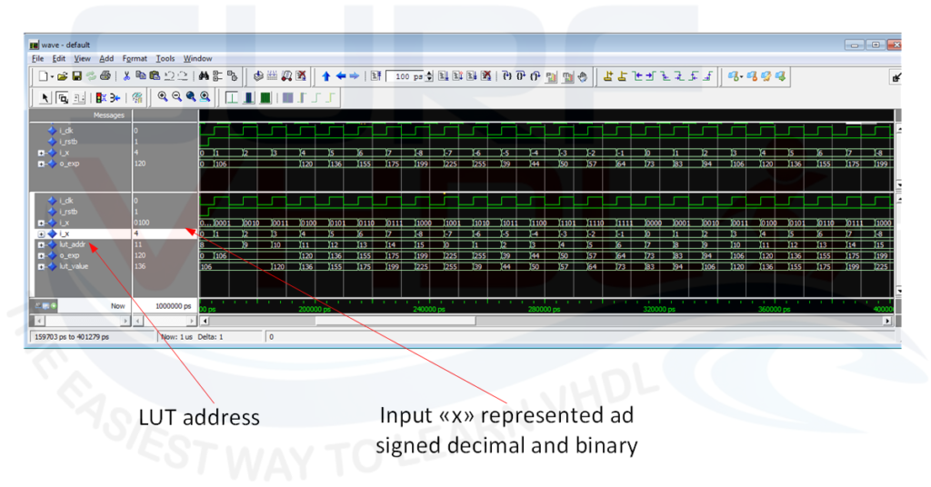
VHDL code simulation for exp(x)
In Figure 5 is reported the simulation for x in the range -8..+7 representing the real value of [-1..+1) as stated before. The simulation reports the input i_x in binary and integer format representation so we can verify in the statement above in a very simple way.
VHDL code implementation of exp(x) on FPGA
Just to confirm that the VHDL code for exp(x) works on FPGA, here below in Figure 6 is reported the layout report of the VHDL code reported above on a Cyclone III FPGA.
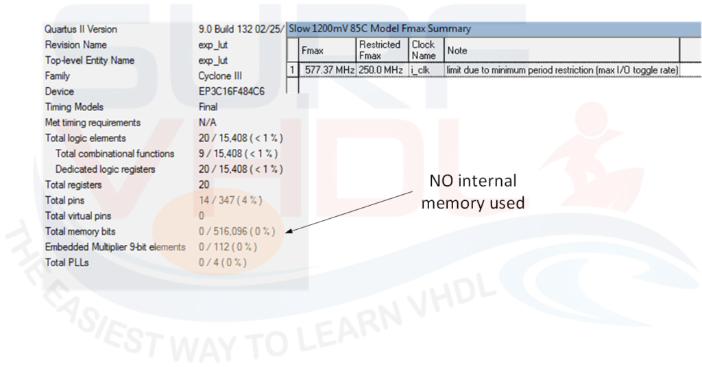
No internal memory seems to be mapped from the area report. In this implementation, the LUT used for the exp(x) implementation is too small so Quartus doesn’t trigger the use of internal memory but implements the LUT using the internal logic.
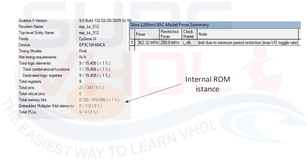
In Figure 7 is reported the layout relative to the same exp(x )function using 9 bit for input i_x quantization and 10 bit for the function output quantization. In this implementation, the number of bits required will be 2^9 * 10 = 512*10 = 5120 bit, so Quartus II trigger the implementation of internal memory macro to store the exp(x) value as clear from the layout area report in Figure 7.
Conclusion
In this post, we found a solution to implement exp(x) in FPGA using VHDL. The example reports the implementation when the argument values of the exponential function are in the range of -1..+1. The quantization of the argument is 4 bit and the exponential function result is quantized with 8-bit. Of course, you can easy modify the code implementing different input range and quantization bit to the function simply modifying the Matlab code provided above.
Reference
https://en.wikipedia.org/wiki/Exponential_function
If you appreciated this post, please help us to share it with your friend.
[social_sharing style=”style-7″ fb_like_url=”https://surf-vhdl.com/compute-exp-x-fpga-using-vhdl” fb_color=”light” fb_lang=”en_US” fb_text=”like” fb_button_text=”Share” tw_lang=”en” tw_url=”https://surf-vhdl.com/compute-exp-x-fpga-using-vhdl” tw_button_text=”Share” g_url=”https://surf-vhdl.com/compute-exp-x-fpga-using-vhdl” g_lang=”en-GB” g_button_text=”Share” linkedin_url=”https://surf-vhdl.com/compute-exp-x-fpga-using-vhdl” linkedin_lang=”en_US” alignment=”center”]
If you need to contact us, please write to: surf.vhdl@gmail.com
We appreciate any of your comment, please post below: