Structural Modeling
The Structural Modeling is very similar to the schematic entry, in this case implemented as text instead of graphically.
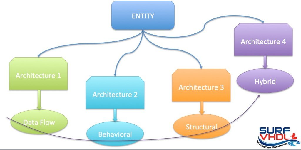
As digital designs become more complex, it becomes less likely that we can use only one of the three-implementation styles seen before. The result is the use of the hybrid VHDL model.

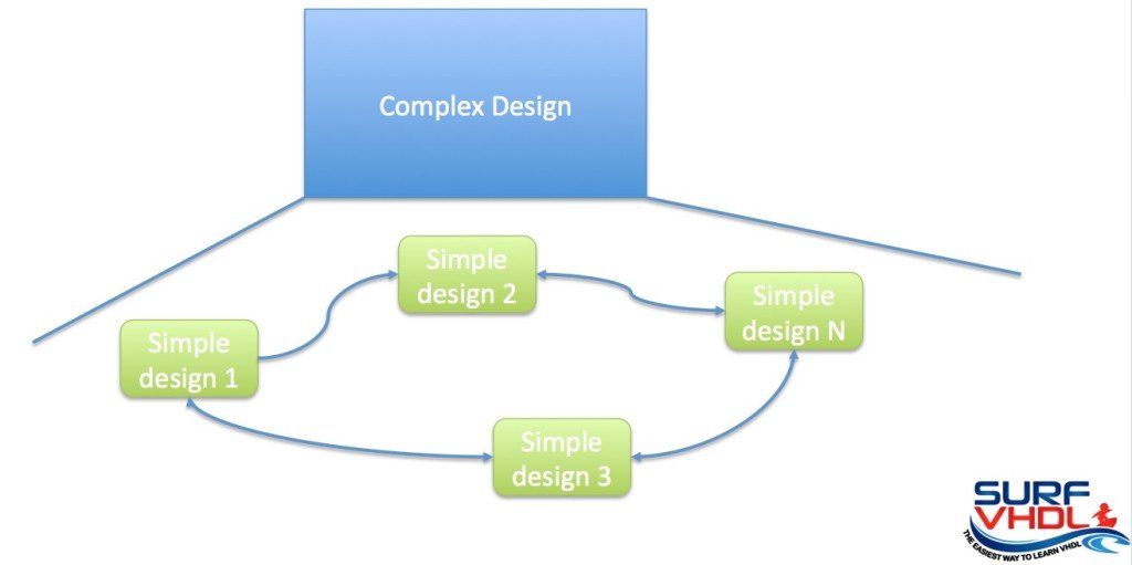
The term structural modeling is the terminology that VHDL uses for the modular design:
if you are designing a complex project, you should split in two or more simple design in order to easy handle the complexity.
The benefits of modular design in VHDL are similar to the benefits that modular design or object-oriented design provides for higher-level computer languages.

Modular designs allow you to pack low-level functionality into modules.
This approach allows a design reuse without the need to reinvent and re-test the wheel every time.
Structural Modeling: Hierarchical approach

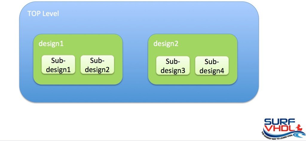
Next step is the hierarchical approach where you can extend beyond the structural coding modeling.
In this case in the TOP Level design, are instantiated a
- design1
- sub-design 1
- sub-design 2
- design2
- sub-design 3
- sub-design 4
Structural architecture declaration
In order to instance a component inside a design, you shall:
- Declare the components in the declarative part of the architecture
- Instance the component in the architecture statement section
The declaration section of the architecture is included between the keyword “is” and “begin”
architecture architecture_name of entity_name is
-- ARCHITECTURE declarative part
begin
-- ARCHITECTURE statement part
end architecture_name;
The statement section or concurrent section of the architecture is included between the keyword “begin” and “end”.
The component declaration to be inserted in the declarative section of the architecture can be summarized as follow:
- Copy the entity declaration relative to the component
- Replace the keyword ”entity” with the keyword ”component”
- Delete keyword ”is”. If you use VHDL 1993 standard or above you can leave the keyword ”is”
- Replace the entity name after the keyword “end” with the keyword “component”.
Component Instantiation
- Copy component declaration in the architecture concurrent area
- Replace the keyword “component” with the instance name and add the keyword “map” after the generic and port clause.
In order to map generic and port
- Replace the comma with the two symbols equal greater than
- Replace the semicolon with colon.
An example will clarify better than thousand explanations.
Structural architecture declaration example
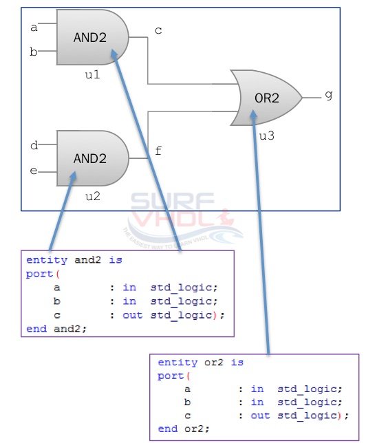
In this example we want to realize the structural implementation the entity and_or in figure below

There are 4 input ports a, b, d, e and one output port g. The instance u1 and u2 of the two AND gate are connected to the u3 using two wire named c and f. Figure above shows the entity declaration for AND2 and OR2 component.
In this moment, we don’t care about the architecture of AND2 and OR2 entity. It could be structural with other component instantiation or behavioral. Let’s see the architecture of the and_or entity in order to understand better the structural instantiation.
entity and_or is
port(
   a : in std_logic;
   b : in std_logic;
   d : in std_logic;
   e : in std_logic;
   g : out std_logic);
end and_or;
architecture and_or_a of and_or is
component and2 -- and2 component declaration
port(
   a : in std_logic;
   b : in std_logic;
   c : out std_logic);
end component;
component or2 -- or2 component declaration
port(
   a : in std_logic;
   b : in std_logic;
   c : out std_logic);
end component;
signal c : std_logic; -- wire used to connect
signal f : std_logic; -- the component
begin
-- and2 component instance
u1: and2
port map(
   a => a,
   b => b,
   c => c);
-- and2 component instance
u2: and2
port map(
   a => d,
   b => e,
   c => f);
-- or2 component instance
u3: or2
port map(
   a => c,
   b => f,
   c => g);
end and_or_a;
In the architecture declarative section we found:
- component declaration AND2 and OR2
- signal declaration c and f
In the statement section, we found the component instantiation.
Now pay attention to the port mapping.
- The port a, b and c mapped in the instance u1 are respectively the entity input port a and b, the internal wire signal c.
- The port a, b and c mapped in the instance u2 are respectively the entity input port d and e, the internal wire signal f.
The instance u3 has the port a mapped on signal c, input port b on signal f and output port c on entity output port g.
As general rule,
the input/output port of an entity are signal inside the architecture.
The input port can be only read, the output port can be only written.
If you try to read from an output port or try to write to an input port the simulator rises an error and stops.