

In Digital Signal Processing, the implementation of transcendental math functions such as trigonometric functions (sine, cosine, tan, atan) or exponential and logarithmic functions is often required. An efficient way, when possible, is to implement an approximation of these functions using a Look-Up Table (LUT), as shown in the sine example in Figure1.
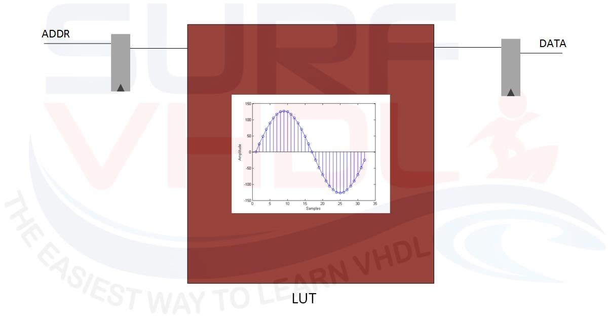
Figure1 – LUT implementing sine function
In modern FPGAs a large amount of RAM/ROM memory is available, so the LUT implementation requires only FPGA memory hardware resources and a few additional registers.
A typical use of LUTs implementing mathematical trigonometric functions is the Direct Digital Synthesis (DDS) of a sinusoidal tone.
A simple DDS architecture is composed of an NCO and a LUT as in Figure2
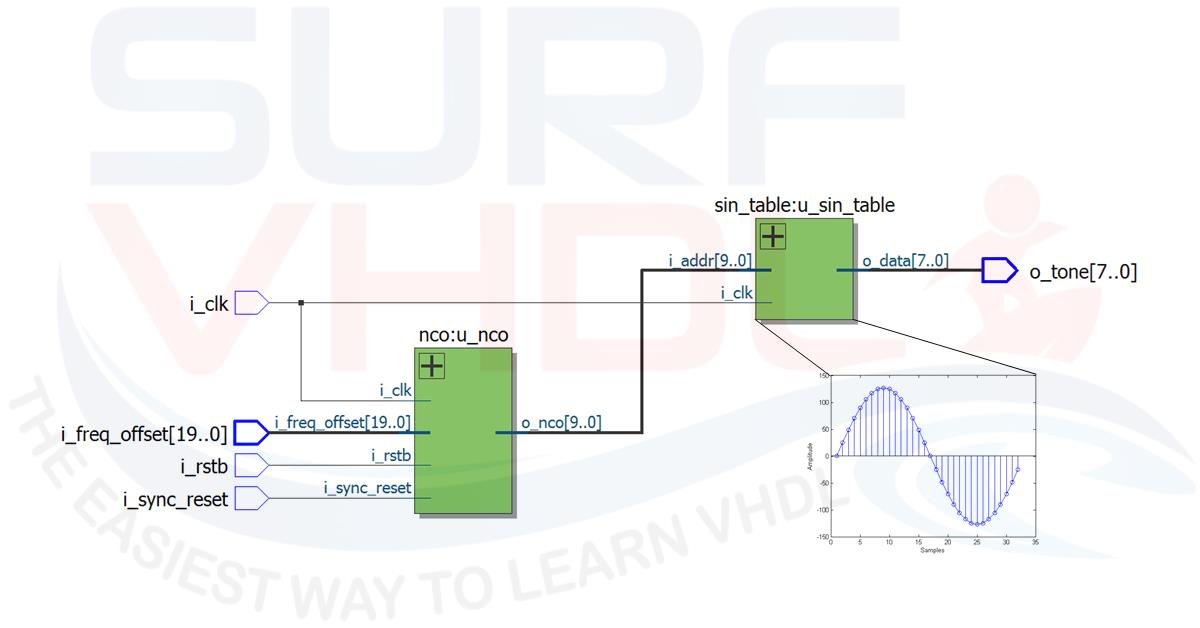
Figure2 – Typical DDS Architecture
By setting the proper NCO frequency word, the output of the LUT generates a tone using the sine samples stored into the LUT. For example, using a system clock of 100 MHz the Figure reports the configuration for a sine wave output frequency of 3.125 MHz with an NCO word 0x08000, and 390.625 KHz after changing NCO frequency word to 0x01000 (3.125 MHz / 8 = 390.625 KHz).
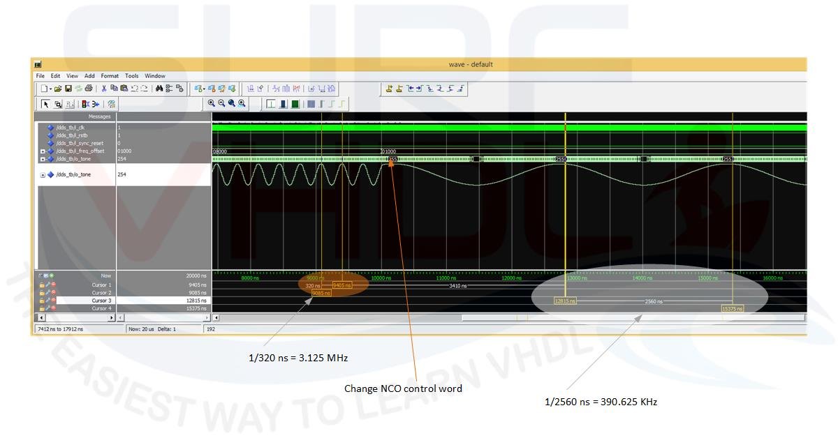
Figure3 – Modelsim Simulation of a DDS
Sine Wave Digital Samples Generation
Methods for Generating Sine LUT Samples
There are several ways to implement a sine wave LUT:
- Using Matlab or equivalent SW
- Using C++ to write the samples to a file
- Using VHDL
Since we are Surf-VHDL, which way do you think we would use? What do you guess?
Maybe Perl 🙂 ?
OK, let’s see how to generate the samples of a sine wave using VHDL testbench. Of course, the VHDL code for generating a sine wave table is not synthesizable code. You can use it to generate the sine / cosine wave samples that you will use to create your LUT or ROM component.
The Math Behind Sine Wave Quantization
Figure4 shows an example of 32 sine wave samples quantized using 8-bit. The X axis shows the sample index and Y axis shows the quantized amplitude.
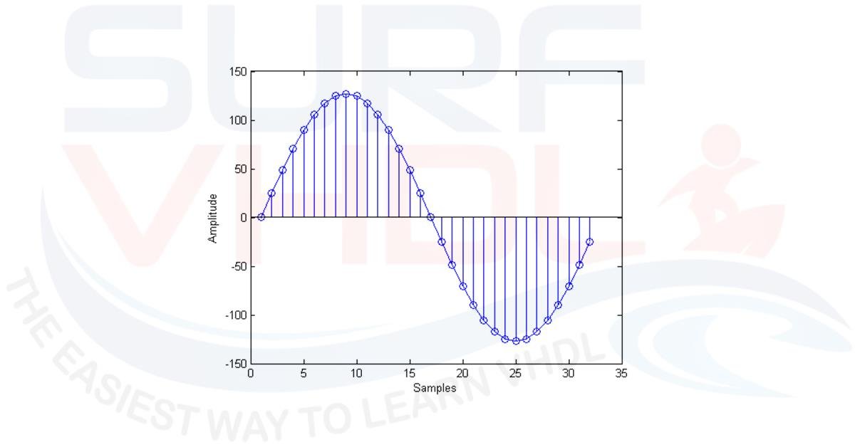
Figure4 – Sine Look Up Table (LUT) example
In other words, we need to generate the quantized version of the following trigonometric sinusoidal function:
sin(2*pi*nT)
where the time vector nT represents the sampling period. If the sampling period is set to one for the sake of convenience, and let NS be the number of samples of sine wave, let’s define the sampling period as 1/NS
the time vector will be represented:
0, 1/NS, 2/NS,.., (NS-1)/NS
VHDL is not as friendly as C++ or Matlab if you need to create such sine vector using type real. In fact, VHDL is a hardware description language, but we want to demonstrate that it can be used also for LUT file generation of a sine / cosine wave samples.
MATLAB Script Example
Using Matlab, a simple code for sine wave generation of 32 samples and maximum quantized value of 127 can be the following:
np=32;
A=127;
t=linspace(0,1-1/np,np);
sin_table = (round(sin(2*pi*t)*A))
This code is very simple and compact.
Using VHDL you need few code lines more…
VHDL Testbench for Sine Samples
Here below there is an example of a VHDL code generating sine wave samples and writing them to an external file. If you change the transcendental function you can generate all the LUTs you need. Then you can use the file containing the sine wave samples to create a VHDL ROM file that you can use inside your design, for example, the DDS implementation of Figure2 above (for a detailed explanation of DDS architecture, see the dedicated post about DDS and NCO).
The sine amplitude is defined as 2^nbit = 256 quantization levels (nbit = 8). If the representation is signed the sine wave amplitude samples will have the range -128 to +127, if the representation is unsigned the sine wave amplitude samples will have the range 0 to 255.
The number of samples is configurable as 2^nsamples = 32
The values of the sine wave table are generated using the quantization_sgn VHDL function. In this function, the test on the positive or negative number is performed. For a positive number the maximum possible value is 2^(NB-1)-1; for a negative number the minimum possible value is -2^(NB-1) where NB is the number of quantization bits.
Understanding the Rounding (IEEE 1076)
To perform rounding before truncation, the floating point value of 0.49 is added (line 24 and 26). This value is 0.49 and not 0.5 as you might use in C++, because standard VHDL (IEEE 1076) uses a round-to-half-even strategy for real types. This means that truncating 0.5 might return 1 instead of 0. Adding 0.49 acts as a safety mechanism to prevent these edge-case rounding errors.
The quantization of sine function as unsigned value is performed by the quantization_uns function that simply recalls the quantization_sgn with the same parameter and returns the value as unsigned simply adding 2^(N-1). The sum is performed by the XOR function on the sign bit.
If you need to review the 2’s complement representation of a binary number, click here.
library ieee;
use ieee.std_logic_1164.all;
use ieee.numeric_std.all;
use ieee.math_real.all;
library std;
use ieee.std_logic_textio.all;
use std.textio.all;

entity write_table is
end write_table;

architecture behav of write_table is

function quantization_sgn(nbit : integer; max_abs : real; dval : real) return std_logic_vector is
variable temp    : std_logic_vector(nbit-1 downto 0):=(others=>'0');
constant scale   : real :=(2.0**(real(nbit-1)))/max_abs;
constant minq    : integer := -(2**(nbit-1));
constant maxq    : integer := +(2**(nbit-1))-1;
variable itemp   : integer := 0;

begin
  if(nbit>0) then
    if (dval>=0.0) then
      itemp := +(integer(+dval*scale+0.49));
    else
      itemp := -(integer(-dval*scale+0.49));
    end if;
    if(itemp<minq) then itemp := minq; end if;
    if(itemp>maxq) then itemp := maxq; end if;
  end if;
  temp := std_logic_vector(to_signed(itemp,nbit));
  return temp;
end quantization_sgn;

function quantization_uns(nbit : integer; max_abs : real; dval : real) return std_logic_vector is
variable temp        : std_logic_vector(nbit-1 downto 0):=(others=>'0');
constant bit_sign    : std_logic_vector(nbit-1 downto 0):=('1',others=>'0');

begin
  temp := quantization_sgn(nbit, max_abs, dval);
  temp := temp xor bit_sign;
  return temp;
end quantization_uns;

constant nsamples  : integer:=5;  -- LOG2 OF THE VALUE
constant nbit      : integer:=8;
constant step      : real := 1.00/real(2**nsamples);

signal clk         : std_logic:='0';
signal sine        : real:=0.0;
signal qsine_sgn   : std_logic_vector(nbit-1 downto 0):=(others=>'0');
signal qsine_uns   : std_logic_vector(nbit-1 downto 0):=(others=>'0');

begin

clk  <= not clk after 1 ns; -- only for wave visualization on modelsim

p_sine_table : process(clk)

file test_vector                       : text open write_mode is "sin_table.dat";
variable row                           : line;
variable count                         : integer :=0;

variable v_sine        : real:=0.0;
variable v_tstep       : real:=0.0;
variable v_qsine_uns   : std_logic_vector(nbit-1 downto 0):=(others=>'0');
variable v_qsine_sgn   : std_logic_vector(nbit-1 downto 0):=(others=>'0');

begin
  if(rising_edge(clk)) then
    -- write table
    if(count<(2**nsamples)) then

      v_sine  := sin(MATH_2_PI*v_tstep);
      v_qsine_uns := quantization_uns(nbit, 1.0,v_sine);
      v_qsine_sgn := quantization_sgn(nbit, 1.0,v_sine);
      v_tstep := v_tstep + step;

      write(row,to_integer(unsigned(v_qsine_uns)), right, 5);
      write(row,',');

      count := count + 1;

      if((count mod 16)=0) then
        writeline(test_vector,row);
      end if;  -- write 16 values per line

      sine  <= v_sine ;
      qsine_uns <= v_qsine_uns;
      qsine_sgn <= v_qsine_sgn;
    else
      assert false
      report "Table Generated"
      severity failure;
    end if;
  end if;
end process p_sine_table;

end behav;
The process “p_sine_table” is used to write the sine samples to the file “sine_table.dat” below:

It is worth noting that in this example we are using a fake or artificial clock only to allow the plot of the sine wave samples on the Modelsim simulation waveform of Figure5.
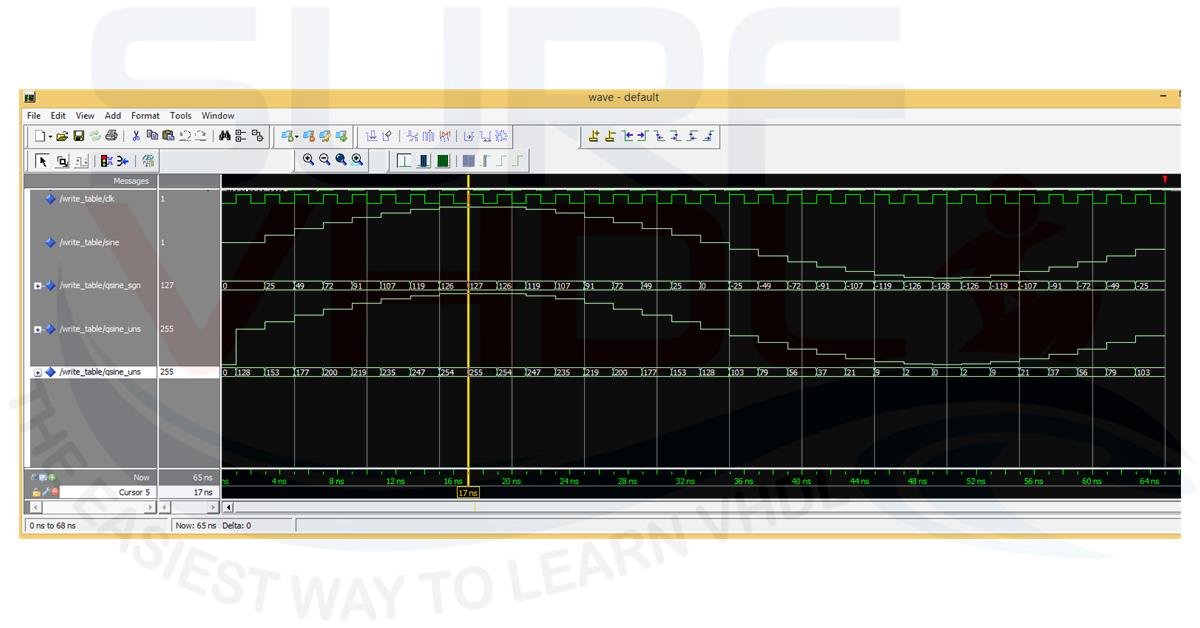
Figure5 – Modelsim simulation of a sine sample generation
Using the Samples in a VHDL ROM
The code prints to file the sine samples as 16 columns per row integer separated by a comma, so you can easily generate the ROM code for a sine waveform as Figure5. Here an example of how to use the sine samples to write the code of a ROM containing the sine values. The ROM address is 5 bit, 32 ROM location and data is represented as 8-bit unsigned value:
library ieee;
use ieee.std_logic_1164.all;
use ieee.numeric_std.all;

entity sin_table is
port (
  i_clk          : in  std_logic;
  i_addr         : in  std_logic_vector(4 downto 0);
  o_data         : out std_logic_vector(7 downto 0));
end sin_table;

architecture rtl of sin_table is
type t_sin_table is array(0 to 31) of integer range 0 to 255;

constant C_SIN_TABLE  : t_sin_table := (
  128,  153,  177,  200,  219,  235,  247,  254,  255,  254,  247,  235,  219,  200,  177,  153,
  128,  103,   79,   56,   37,   21,    9,    2,    0,    2,    9,   21,   37,   56,   79,  103);

begin

--------------------------------------------------------------------

p_table : process(i_clk)
begin
  if(rising_edge(i_clk)) then
    o_data  <= std_logic_vector(to_unsigned(C_SIN_TABLE(to_integer(unsigned(i_addr))),8));
  end if;
end process p_table;

end rtl;
You can use the VHDL code above to generate all the transcendental functions you need in your VHDL design simply modifying the function, number of bits per sample and quantization. The figure shows the RTL view and post-layout report of the VHDL code for 1024 samples 8-bit data sine ROM, using Intel Quartus Prime
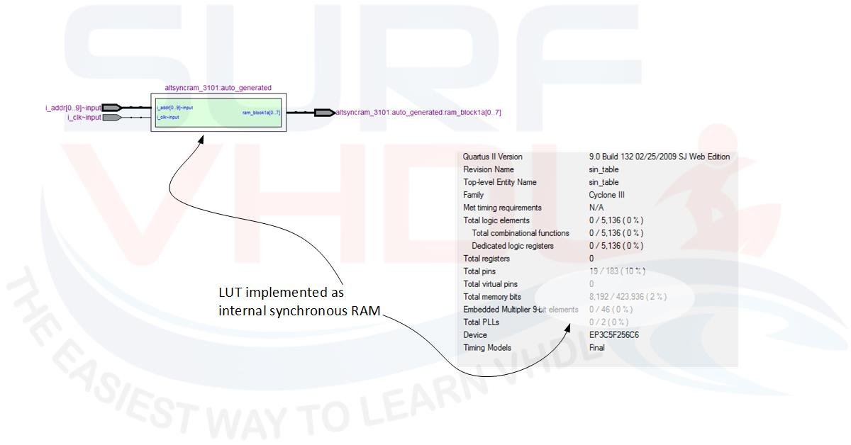
Figure6 – Quartus II Layout of 1kx8 ROM memory RTL View and report
If you appreciated this post, please help us to share it with your friend.
If you need to contact us, please write to: surf.vhdl@gmail.com