

Basic notion on FIFO (First-In First-Out)
FIFO means First-In First-Out. A FIFO is a structure used in hardware or software applications when you need to buffer data.
Basically, you can think of a FIFO as a bus queue in London.
The first person to arrive is the first to catch the bus…

Figure1 – FIFO example at bus Stop
Of course, this example is valid only in London or in Japan; in other countries, it might not apply 🙂
How can you implement a FIFO structure?
As a basic idea, you can imagine a FIFO as a pipe where the first element entering the pipe is the first element to exit, as shown in Figure2.
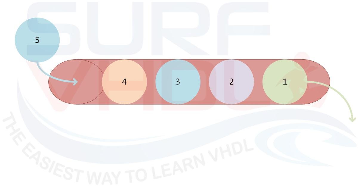
Figure2 – FIFO representation as pipe
In particular, you can implement a FIFO structure using a memory buffer able to store your elements, plus a write pointer and a read pointer to write data to and read data from the current memory addresses.
The maximum number of elements that you can store inside that memory is the FIFO depth.
The FIFO Architecture
The FIFO architecture implementation for both hardware (VHDL or Verilog) and software is very similar. Of course, in the hardware implementation of a FIFO, you must take into account some additional issues not present in software implementations, which we will see later.
In this post, we want to address first the basic architecture of a FIFO that is common in either software (C++, C#) or hardware (VHDL, Verilog) implementations.
In Figure3, a memory is represented that can store up to 8 elements; the memory address range is 0 to 7. The two pointers, wr_ptr and rd_ptr, are the write and read address pointers, respectively.
At the start, the write and read pointers are set to address zero (Figure3 – A). The difference between the two pointers is zero, i.e.
wr_ptr-rd_ptr = 0
which means the FIFO is empty.
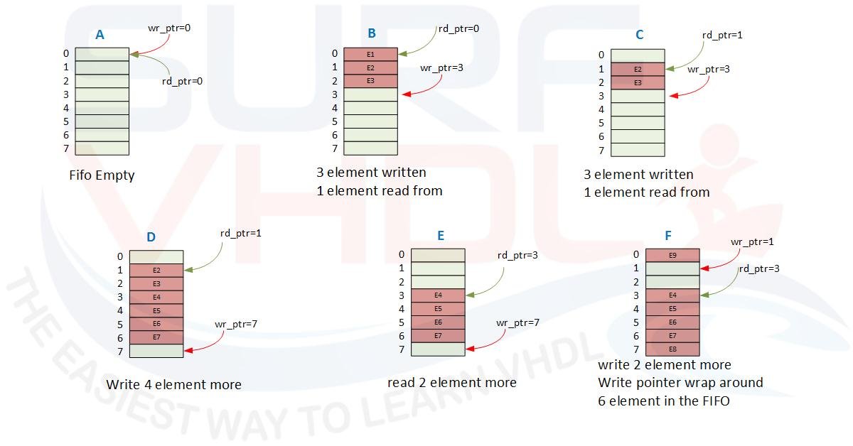
Figure3 – FIFO evolution using memory example
Circular Buffer: A Memory Example
Now, let’s write 3 elements into the FIFO (Figure3 – B):
wr_ptr = 3, points to the next valid location
rd_ptr = 0

wr_ptr-rd_ptr = 3-0 = 3
The number of elements is 3.
If we read an element from the FIFO’s zero memory address (Figure3 – C), Elem1 is read from the FIFO, and
rd_ptr = 1;
In this case, the number of elements in the FIFO is
3-1 = 2
Now fill the FIFO up to 6 elements (Figure3 – D):
wr_ptr=7
rd_ptr=1

wr_ptr-rd_ptr = 7-1 = 6
Read another 2 elements (Figure – E)
wr_ptr-rd_ptr = 7-3 = 4
What happens if we write another 2 elements? The current wr_ptr = 7; adding 2 elements gives 7+2=9, which is greater than the FIFO depth!
Of course, we need to manage the memory as a circular buffer, so the write pointer will be (Figure3 – F):
(7+2) % 8 = 1
In this case, how many data are available in the FIFO?
wr_ptr-rd_ptr = 1-3 = -2
What’s up, we have -2 data??
As stated, the memory is a circular buffer, so the correct expression is:
(wr_ptr - rd_ptr + FIFO_DEPTH) % FIFO_DEPTH = (1-3+8)%8 = (6) % 8 = 6
If you count the number of elements inside the FIFO, it is 6.
To summarize, the number of data elements in a FIFO of depth FIFO_DEPTH is
N = (wr_ptr - rd_ptr + FIFO_DEPTH) % FIFO_DEPTH
When N
Note: N in the equation above is 0 (zero) both when the FIFO is empty and when the FIFO is full.
So how can we detect EMPTY or FULL condition?
We have to check if the write pointer is catching up to the read pointer or vice versa:
- if the write pointer is catching up to the read pointer => N=0 means FIFO FULL
- if the read pointer is catching up to the write pointer => N=0 means FIFO EMPTY
This is the basic architecture you must know in order to understand how a FIFO works.
Interactive Circular Buffer
Depth = 8. Try writing and reading data to see pointers in action.
In software implementation, a FIFO can be implemented with a custom depth without particular constraints.
Here you can find a FIFO definition and its software implementation on Wikipedia.
FIFO Hardware Implementation Considerations
When you have to implement a FIFO in an FPGA or ASIC, some considerations should be taken into account in order to simplify the realization.
FIFO Depth
FIFO depth should be equal to a power of two.
As we have seen above, the number of data elements in a FIFO is
N = (wr_ptr - rd_ptr + FIFO_DEPTH) % FIFO_DEPTH
The modulo operation in hardware is very demanding in terms of logic gates unless FIFO_DEPTH = 2^N, in which case you don’t need any check.
Maybe an example will clarify.
In the FIFO above, the FIFO_DEPTH = 8 (i.e., the address pointer can get values from 0 to 7). In order to represent the address value, only 3 bits are needed.
If you need further details on the binary representation of a number you can read this post.
Let’s see what happens in the case of
(wr_ptr - rd_ptr + FIFO_DEPTH) % FIFO_DEPTH = (1-3+8)%8 = (6) % 8 = 6
Representing wr_ptr and rd_ptr using three bits:
wr_ptr = "001" (+1d)
rd_ptr = "101" (-3d)

wr_ptr - rd_ptr =
"001" (+1) +
"101" (-3) =
-----------------
"110" = 6
The modulo operation is self-contained in 2’s complement arithmetic.
So as a rule of thumb, if you use a power of two for FIFO_DEPTH, the number of data elements in a circular buffer is simply given by
(wr_ptr – rd_ptr)
represented with log2(FIFO_DEPTH) number of bits.
In the example above
2^3 = 8
How to Implement a FIFO in an FPGA
Until now, we have considered the general FIFO architecture:
- memory element
- write pointer
- read pointer
- the relationship between write and read pointer.
When you deal with FPGA or ASIC hardware implementation, the going gets tough!
A typical FIFO FPGA or ASIC hardware architecture (Figure4 ) is implemented using a
- DUAL-PORT RAM
- write counter to address the write side of the RAM
- read counter to address the read side of the RAM
- control logic aiming to update the write counter at each data write into the RAM, and the read counter every time data is read from the RAM.
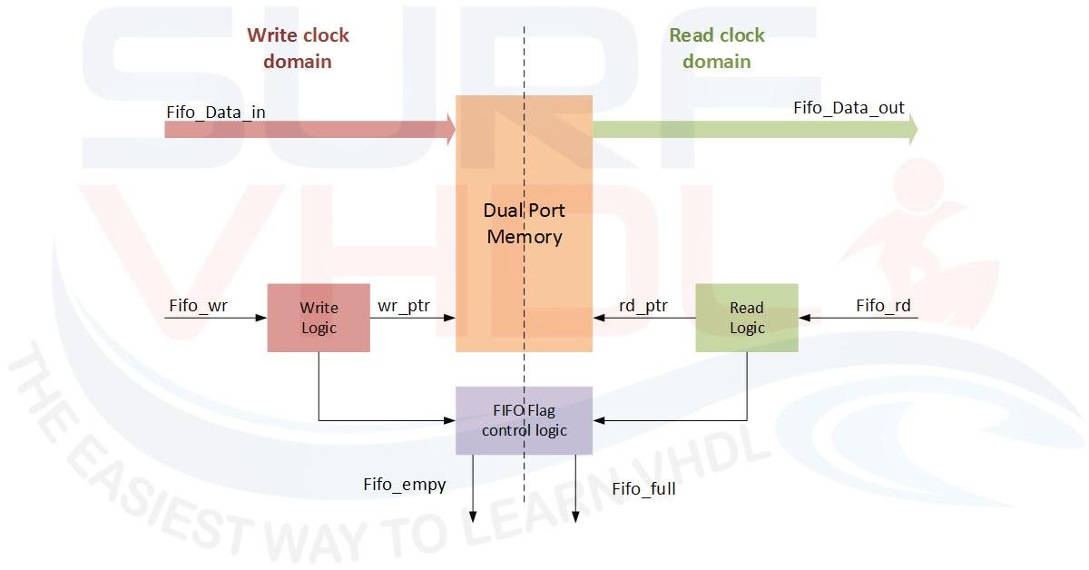
Figure4 – Example of FIFO FPGA or ASIC hardware architecture
FIFO Flags: Empty, Full, and Almost Empty/Full
Moreover, the control logic shall drive the FIFO flags:
- FIFO-Empty: flags that no data is present inside the FIFO RAM
- FIFO-Full: flags that no data can be written to the FIFO memory
- FIFO-Almost Empty/Full: used if required
A typical use of the FIFO-Almost Empty flag is when the FIFO is used to buffer an input data stream for a device where the input and output data throughput is the same but the timing is different, as seen in Figure5:
- Input as burst data;
- Output as continuous data.
- The FIFO is used to buffer the minimum number of burst data elements to guarantee continuous reading from the FIFO without interruption.
In this case, the FIFO Read Control Logic block checks for the almost empty flag going high and sets the FIFO read control signal to read continuously from the FIFO.
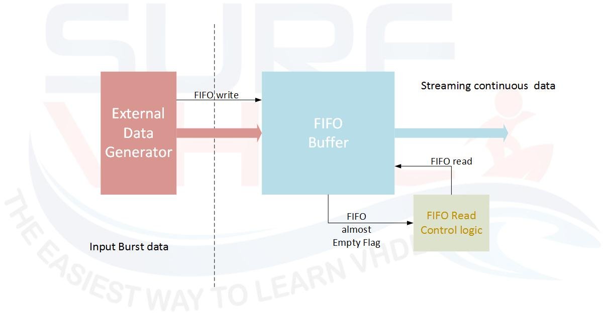
Figure5 – Typical example of FIFO almost empty use case
A typical use of the FIFO-Almost Full flag is for a module connected to an output FIFO generating streaming data at a higher rate than the output; the almost full flag is used to block data generation, as in Figure6.
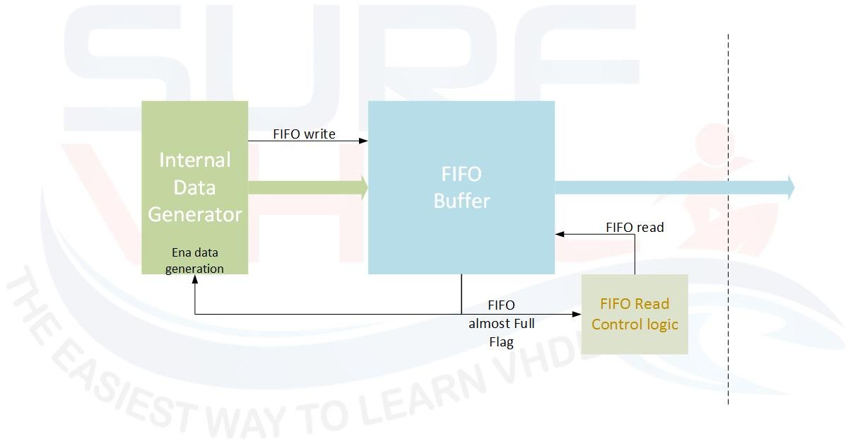
Figure6 – Typical example of FIFO almost full flag use case
Even in this case, the FIFO Read Control Logic block checks for the almost full flag going high and sets the FIFO read control signal to read continuously from the FIFO. The same almost full flag is used to stop data generation from the Internal Data Generator module. The overall result is that the data written into the FIFO is generated as a burst, while at the FIFO output, the data is streamed continuously.
Asynchronous FIFO and Clock Domain Crossing
In both cases above, the FPGA or ASIC hardware implementation of the FIFO can involve two potentially different clock domains. If different clock domains are required, the FIFO shall be designed as an asynchronous FIFO.
The FIFO implementation becomes more complex if the write side and read side are driven by different clock domains.
The write clock domain side will update the write pointer address and write data to the memory half clocked by the write clock.
The read clock domain side will update the read pointer address and read data from the memory half clocked by the read clock.
In this case, particular attention must be paid to EMPTY/FULL flag updating: the FIFO flags are updated across the two clock domains. There are several techniques used to implement Clock Domain Crossing (CDC). In FPGA or ASIC, the most used strategy is to use Gray code for the write and read counters.
Why use Gray code instead of standard binary? In standard binary counting, transitioning from 3 to 4 changes 3 bits simultaneously (011 → 100). If the destination clock samples the data right in the middle of this transition, it might capture a corrupted value (a “glitch”). In Gray code, the pointer changes only one bit per increment. This counter update strategy ensures that, during the write/read cross-check at two different clocks, any sampling error is minimized.
CDC Waveform: The "3 to 4" Transition
Because logic signals have slight routing delays (skew), bits don't change at the exact same picosecond. Move the scrubber to see how this creates a glitch in standard Binary.
Sampled Binary
Sampled Gray Code
Generally, you should not write VHDL or Verilog code for a FIFO from scratch. Instead, you should use vendor macros that guarantee correct FIFO functionality for both synchronous and asynchronous write and read clocks (i.e., whether or not you use the same clock for the write and read sides).
Here you can find an example of FIFO implementation in Altera technology;
Here you can find an example of FIFO implementation in Xilinx technology;
Conclusion
To wrap things up, a FIFO (First-In First-Out) is an essential structure for data buffering in both software and hardware. Whether you picture it as a bus queue in London or a pipe, the core concept remains the same: data exits in the exact order it enters.
When moving to hardware (FPGA/ASIC), designing a FIFO requires managing a circular buffer with dual-port RAM and carefully handling read and write pointers. Things get especially tricky when dealing with separate clock domains (asynchronous FIFOs), where techniques like Clock Domain Crossing and Gray-coded pointers become fundamental to avoid data corruption and glitches.
If you appreciated this post, please help us to share it with your friend.
If you need to contact us, please write to: surf.vhdl@gmail.com