
When simulating a VHDL design, it is very useful to be able to save simulation results. For example, if you need to compare the simulation results with reference test vectors, or simply to document the simulation in a test report.
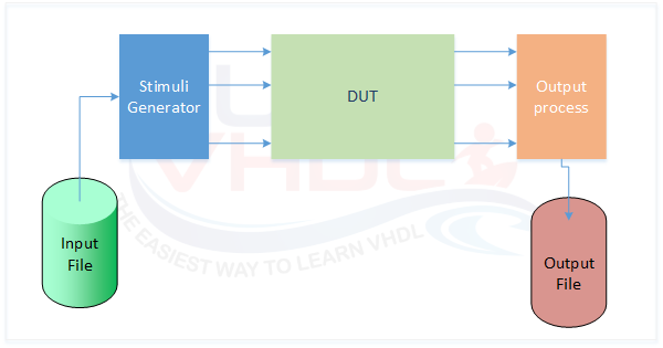
Write File Test Bench Architecture
Why Use TextIO in VHDL Testbenches?
While waveform viewers are excellent for debugging, relying solely on them becomes impractical for complex designs. Exporting data to an ASCII file allows you to automatically process simulation results using external tools like MATLAB, Python, or Excel.
VHDL provides predefined libraries that allow writing to an output ASCII file in a simple way. The TextIO library is a standard library that provides all the procedures to read from or write to a file.
These procedures cannot be used in synthesizable RTL VHDL code — no file handling is possible on a silicon device using simple RTL VHDL code, but they are very useful in test bench design.
Basic Syntax: Opening and Writing to a File
There are several different ways to open a file and write to it. In VHDL, files are handled as an array of lines. An example of VHDL syntax to write to a file is:
-- Declare and Open file in write mode:
file file_handler     : text open write_mode is "filename.dat";
Variable row          : line;
Variable v_data_write : integer;

-- Write value to line
write(row, v_data_write);

-- Write line to the file
writeline(file_handler, row);
The last action (writeline) is used to write the desired value from the line to the file. If v_data_write is an integer value, the write procedure will try to write an integer value to the output line; if it is a real value, the procedure will try to write a real number, and so on.
In this VHDL code snippet, the file is opened during the file declaration.
Formatting the Output: Justification and Width
When writing values, you can pass additional parameters to format your text columns perfectly. The standard syntax allows you to define the justification (right or left) and the field width (number of characters):
write(row, v_data_write, right, 15);
In this example, right means the text will be right-justified, and 15 indicates that the value will occupy exactly 15 characters. If the value is shorter, it will be padded with spaces. This is incredibly useful for creating clean, readable tabular data in your output file.
Interactive VHDL TextIO Line Builder
To make things easier, use the interactive widget below to generate the exact VHDL code for your formatted output. Adjust the procedure, field width, and justification to see a live preview of how the data will be aligned in your text file!
Appending to an Existing File & Writing CSV Headers
By default, using write_mode will overwrite the existing file every time the simulation restarts. If you want to add new lines to an already existing file without deleting its content, you should open it using append_mode:
file file_handler : text open append_mode is "filename.dat";
Another very common scenario is creating a CSV (Comma Separated Values) file for Excel. To do this, it is highly recommended to write a header row at the beginning of your simulation (usually before the main clock loop starts):
-- Writing a CSV header
write(row, string'("Time, Signal_A, Signal_B"));
writeline(file_handler, row);
Complete VHDL TextIO Process Example
A complete example of a process that writes to a file is given below:
-- procedure WRITE(L : inout LINE; VALUE : in integer; JUSTIFIED: in SIDE := right; FIELD: in WIDTH := 0);
.
.
signal o_valid        : std_logic;
signal o_add          : std_logic_vector(7 downto 0);
.
.
.
p_dump  : process(i_rstb,i_clk)

file test_vector      : text open write_mode is "output_file.txt";
variable row          : line;

begin


  if(i_rstb='0') then

  ------------------------------------
  elsif(rising_edge(i_clk)) then

    if(o_valid = '1') then

      write(row,o_add, right, 15);

      write(row,conv_integer(o_add), right, 15);

      hwrite(row,o_add, right, 15);

      hwrite(row,"00000000"&o_add, right, 15);

      writeline(test_vector,row);

    end if;
  end if;
end process p_dump;
The code above implements a process that writes to an output file at each clock cycle the following values:
- Column 1: 8-bit value
- Column 2: integer values;
- Column 3: 8-bit hexadecimal value
- Column 4: 16-hexadecimal value
Data is written if control signal “o_valid” is ‘1’. This code writes all the values right justified and each column contains 15 characters.
Expected Output Format
The output file will have the following format:
00000011              3             03           0003
00001010             10             0A           000A
00000010              2             02           0002
01011010             90             5A           005A
TextIO Quick Reference: Standard Write Procedures
Below are the procedures you can find in the IEEE TextIO standard library to write different types of values to a file:
procedure WRITELINE(file f : TEXT; L : inout LINE);

procedure TEE (file F :       TEXT; L : inout LINE);

procedure WRITE(L : inout LINE; VALUE : in bit;
    JUSTIFIED: in SIDE := right;
    FIELD: in WIDTH := 0);

procedure WRITE(L : inout LINE; VALUE : in bit_vector;
    JUSTIFIED: in SIDE := right;
    FIELD: in WIDTH := 0);

procedure WRITE(L : inout LINE; VALUE : in BOOLEAN;
    JUSTIFIED: in SIDE := right;
    FIELD: in WIDTH := 0);

procedure WRITE(L : inout LINE; VALUE : in character;
    JUSTIFIED: in SIDE := right;
    FIELD: in WIDTH := 0);

procedure WRITE(L : inout LINE; VALUE : in integer;
    JUSTIFIED: in SIDE := right;
    FIELD: in WIDTH := 0);

procedure WRITE(L : inout LINE; VALUE : in real;
    JUSTIFIED: in SIDE := right;
    FIELD: in WIDTH := 0;
    DIGITS: in NATURAL := 0);

procedure WRITE (L      : inout LINE; VALUE : in REAL;
         FORMAT : in    STRING);

procedure WRITE(L : inout LINE; VALUE : in string;
    JUSTIFIED: in SIDE := right;
    FIELD: in WIDTH := 0);

procedure WRITE(L : inout LINE; VALUE : in time;
    JUSTIFIED: in SIDE := right;
    FIELD: in WIDTH := 0;
    UNIT: in TIME := ns);

alias SWRITE is WRITE [LINE, STRING, SIDE, WIDTH];
alias STRING_WRITE is WRITE [LINE, STRING, SIDE, WIDTH];
alias BWRITE is WRITE [LINE, BIT_VECTOR, SIDE, WIDTH];
alias BINARY_WRITE is WRITE [LINE, BIT_VECTOR, SIDE, WIDTH];

procedure OWRITE (L         : inout LINE; VALUE : in BIT_VECTOR;
        JUSTIFIED : in    SIDE := right; FIELD : in WIDTH := 0);
alias OCTAL_WRITE is OWRITE [LINE, BIT_VECTOR, SIDE, WIDTH];
procedure HWRITE (L         : inout LINE; VALUE : in BIT_VECTOR;
        JUSTIFIED : in    SIDE := right; FIELD : in WIDTH := 0);
alias HEX_WRITE is HWRITE [LINE, BIT_VECTOR, SIDE, WIDTH];
If you appreciated this post, please share it with your friends.
If you need to contact us, please write to: surf.vhdl@gmail.com