

VHDL FOR-LOOP statement
Get the complete VHDL code from this article.
VHDL Iterative Statement
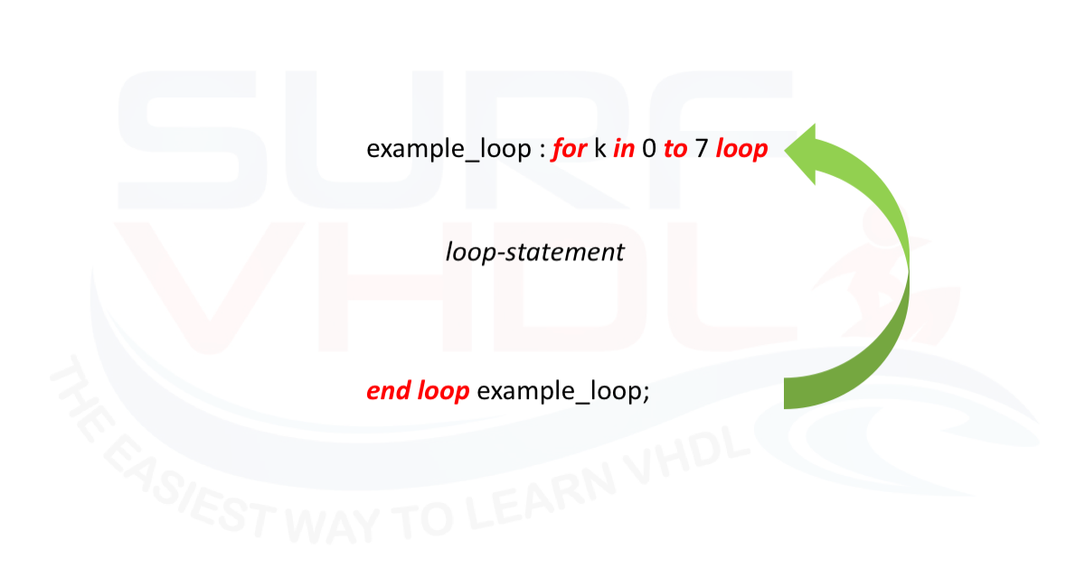
In VHDL the FOR-LOOP statement is a sequential statement that can be used inside a process statement as well as in subprograms.
The FOR-LOOP statement is used whenever an operation needs to be repeated.
In VHDL behavioral code, i.e. when we write a VHDL code of a test bench in a pure behavioral model, the FOR-LOOP usage statement can be considered as a common SW implementation of a loop statement as in the other SW languages.
In VHDL RTL the FOR-LOOP statement shall be used taking into account the final hardware implementation.
A critical difference from software loops is that in VHDL RTL the FOR-LOOP range must be static (known at synthesis time, e.g. 0 to 7). The synthesizer unrolls the loop, replicating the hardware logic for each iteration. This means the loop range directly determines the amount of hardware generated — a large range can lead to excessive area usage.
This consideration, of course, is always valid in any VHDL code implementation.
The FOR-LOOP statement is more difficult to visualize as a final result in HW implementation.
In the next section, we will learn how the FOR-LOOP statement is mapped into hardware logic using a couple of examples.
The FOR-LOOP VHDL BNF syntax is:
loop_statement ::= [ loop_label : ]
  for loop_parameter_specification loop sequence_of_statements

  end loop [ loop_label ] ;


for item in 1 to last_item loop
  table(item) := 0;
end loop;
The loop label is optional but is a good practice to use since the VHDL code becomes more readable even if the VHDL source file becomes larger (nowadays the space on the disk is cheaper than some years ago, so it is not an issue).
FOR-LOOP VHDL example
A typical example of FOR-LOOP statement is a parity checker.
A simple implementation of a parity checker on an 8-bit register can be implemented using an 8 input XOR gate as in Figure 1.
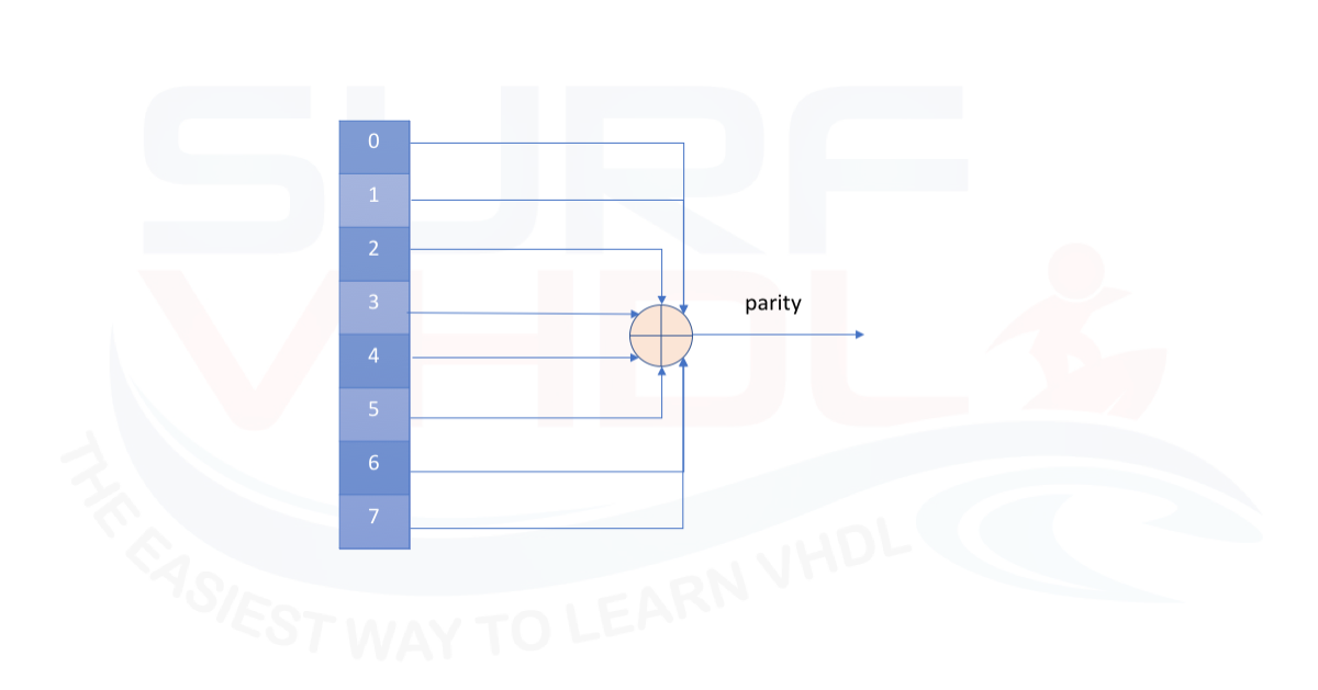
Figure 1 – 8-bit parity checker
The only problem is that not all technologies offer an 8-input XOR gate.
A simple possible solution could be to cascade 7 XOR gates where the output of the k-th gate is the input of the (k+1) XOR gate as in Figure 2.
library IEEE;
use IEEE.std_logic_1164.all;
use IEEE.numeric_std.all;

entity parity_check is
port(
  i_clk             : in  std_logic;
  i_data            : in  std_logic_vector(7 downto 0);
  o_parity          : out std_logic);
end parity_check;

architecture rtl of parity_check is

signal r_data            : std_logic_vector(7 downto 0);

begin

p_parity_check : process (i_clk)
variable vparity           : std_logic;
begin
  if rising_edge(i_clk) then
    r_data  <= i_data;

    vparity := '0';
    l_parity : for k in 0 to r_data'length-1 loop
      vparity := vparity xor r_data(k);
    end loop l_parity;

    o_parity <= vparity;
  end if;
end process p_parity_check;

end rtl;
VHDL code for 8-bit parity checker using FOR-LOOP
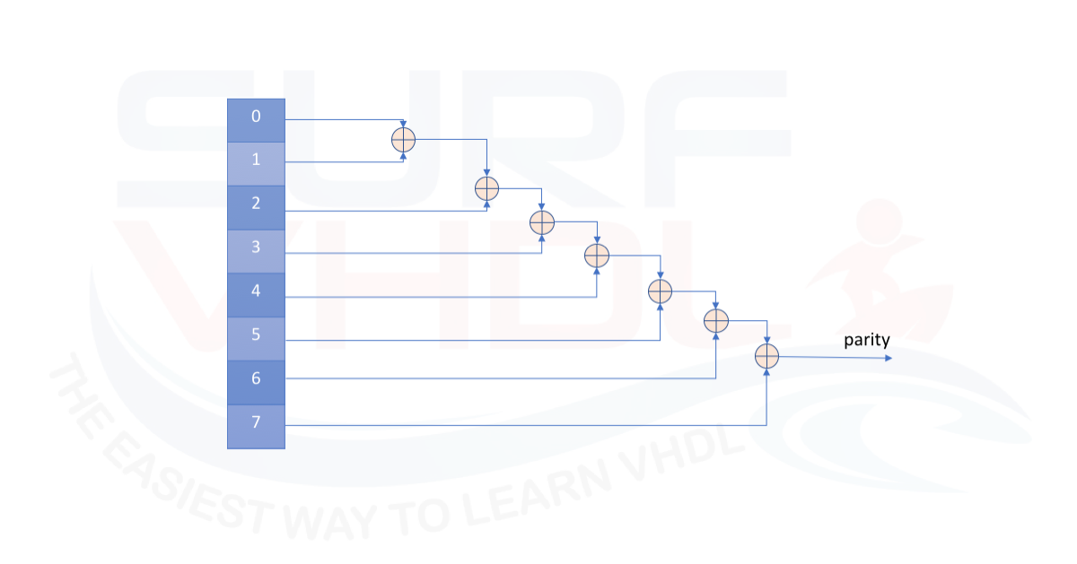
Figure 2 – 8-bit parity checker using 2-input cascaded XOR gate
Another example is represented by a VHDL code that implements an accumulator.
The architecture is very similar to a parity checker (that can be seen as an accumulator over GF(2), i.e. Galois Field of order 2). The 8-bit values are added together using the temporary variable for accumulation and then assigned to the entity output.
A possible VHDL code is reported below:
library IEEE;
use IEEE.std_logic_1164.all;
use IEEE.numeric_std.all;

entity accumulator is
port(
  i_clk             : in  std_logic;
  i_data0           : in  std_logic_vector(7 downto 0);
  i_data1           : in  std_logic_vector(7 downto 0);
  i_data2           : in  std_logic_vector(7 downto 0);
  i_data3           : in  std_logic_vector(7 downto 0);
  i_data4           : in  std_logic_vector(7 downto 0);
  i_data5           : in  std_logic_vector(7 downto 0);
  i_data6           : in  std_logic_vector(7 downto 0);
  i_data7           : in  std_logic_vector(7 downto 0);
  o_acc             : out std_logic_vector(10 downto 0));
end accumulator;

architecture rtl of accumulator is

type t_data  is array (0 to 7) of signed(10 downto 0);
signal r_data            : t_data;

begin

p_accumulator : process (i_clk)
variable vacc              : signed(10 downto 0);
begin
  if rising_edge(i_clk) then
    r_data(0)  <= to_signed(to_integer(signed(i_data0)),11);
    r_data(1)  <= to_signed(to_integer(signed(i_data1)),11);
    r_data(2)  <= to_signed(to_integer(signed(i_data2)),11);
    r_data(3)  <= to_signed(to_integer(signed(i_data3)),11);
    r_data(4)  <= to_signed(to_integer(signed(i_data4)),11);
    r_data(5)  <= to_signed(to_integer(signed(i_data5)),11);
    r_data(6)  <= to_signed(to_integer(signed(i_data6)),11);
    r_data(7)  <= to_signed(to_integer(signed(i_data7)),11);

    vacc := (others=>'0');
    l_acc : for k in 0 to r_data'length-1 loop
      vacc := vacc + r_data(k);
    end loop l_acc;

    o_acc <= std_logic_vector(vacc);
  end if;
end process p_accumulator;

end rtl;
VHDL code accumulator using FOR-LOOP with no optimization
A more optimized architecture of the adder for the 8 values is represented in Figure 4.
In this case, the VHDL code implements a cascade of balanced adder equalizing the delay over the adder structure. A possible VHDL code description using FOR-LOOP approach of the adder cascade is given below.
library IEEE;
use IEEE.std_logic_1164.all;
use IEEE.numeric_std.all;

entity accumulator_better is
port(
  i_clk             : in  std_logic;
  i_data0           : in  std_logic_vector(7 downto 0);
  i_data1           : in  std_logic_vector(7 downto 0);
  i_data2           : in  std_logic_vector(7 downto 0);
  i_data3           : in  std_logic_vector(7 downto 0);
  i_data4           : in  std_logic_vector(7 downto 0);
  i_data5           : in  std_logic_vector(7 downto 0);
  i_data6           : in  std_logic_vector(7 downto 0);
  i_data7           : in  std_logic_vector(7 downto 0);
  o_acc             : out std_logic_vector(10 downto 0));
end accumulator_better;

architecture rtl of accumulator_better is
constant C_NUMDATA    : integer := 8;
type t_data  is array (0 to C_NUMDATA-1) of signed(10 downto 0);
signal r_data            : t_data;

begin

p_accumulator_better : process (i_clk)
type t_data_temp4  is array (0 to (C_NUMDATA/2)-1) of signed(10 downto 0); -- 4
type t_data_temp2  is array (0 to (C_NUMDATA/4)-1) of signed(10 downto 0); -- 2
variable vacc4              : t_data_temp4;
variable vacc2              : t_data_temp2;
begin
  if rising_edge(i_clk) then
    r_data(0)  <= to_signed(to_integer(signed(i_data0)),11);
    r_data(1)  <= to_signed(to_integer(signed(i_data1)),11);
    r_data(2)  <= to_signed(to_integer(signed(i_data2)),11);
    r_data(3)  <= to_signed(to_integer(signed(i_data3)),11);
    r_data(4)  <= to_signed(to_integer(signed(i_data4)),11);
    r_data(5)  <= to_signed(to_integer(signed(i_data5)),11);
    r_data(6)  <= to_signed(to_integer(signed(i_data6)),11);
    r_data(7)  <= to_signed(to_integer(signed(i_data7)),11);

    l_acc4 : for k in 0 to (C_NUMDATA/2)-1 loop
      vacc4(k) := r_data(2*k) + r_data(2*k+1);
    end loop l_acc4;

    l_acc2 : for k in 0 to (C_NUMDATA/4)-1 loop
      vacc2(k) := vacc4(2*k) + vacc4(2*k+1);
    end loop l_acc2;

    o_acc <= std_logic_vector(vacc2(0) + vacc2(1));
  end if;
end process p_accumulator_better;

end rtl;
VHDL code accumulator using FOR-LOOP with balanced adder tree optimization
Adder Architecture Comparison
Toggle to see how FOR-LOOP style affects the critical path
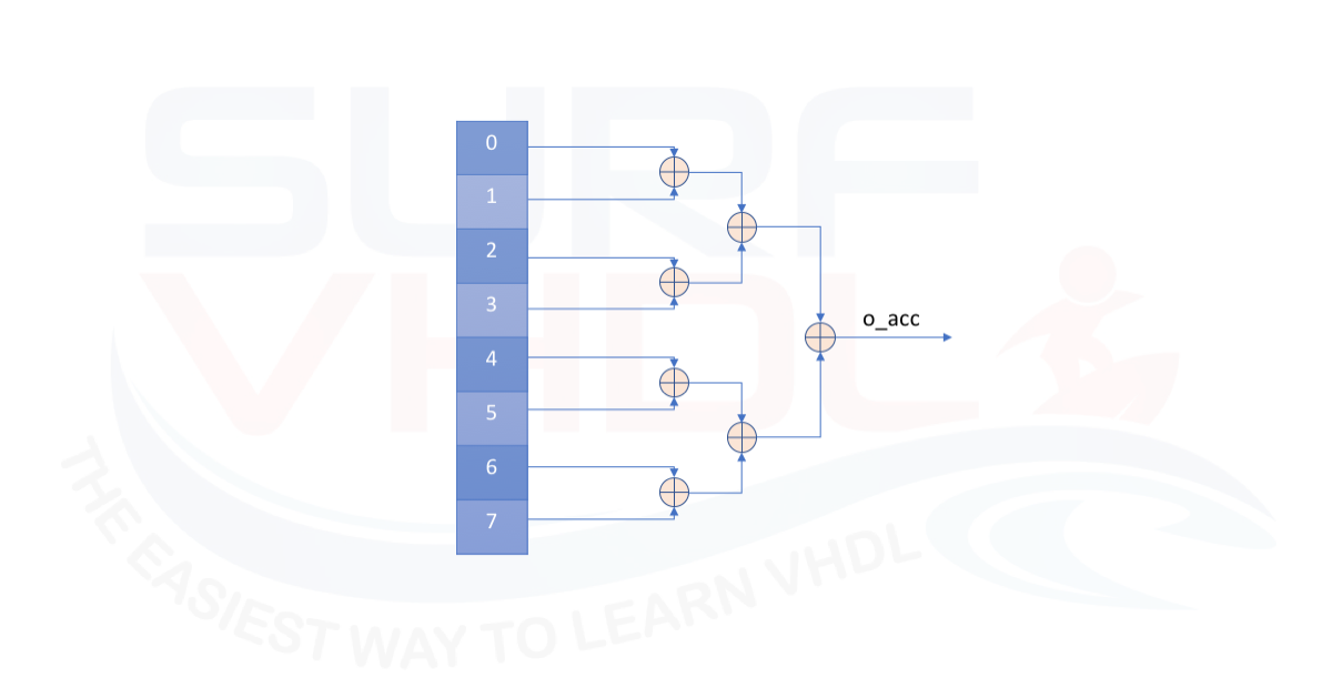
Figure 4 – 8 input balanced tree signed adder
Layout consideration on FOR LOOP
Some considerations should be done on the VHDL code above.
If we try to layout either the parity check VHDL code or the accumulator VHDL code the VHDL synthesizer can optimize our code implementing the best hardware structure for the device we are using.
Altera/Intel Implementation
Altera Quartus II implements the different VHDL descriptions of the adder in the same way. As clear from Figure 5, the RTL viewer reports different implementation for the VHDL code of cascaded adder or balanced tree adder.
In the first case, the adder tree is not balanced, in the second case the addition is performed using a balanced adder tree.
In both cases, the Fitter and netlist optimizer implements on an Altera/Intel Cyclone II the same hardware mapping as clear from the fitter report and timing analysis in Figure 6.
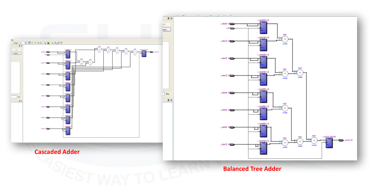
Figure 5 – Quartus II RTL viewer
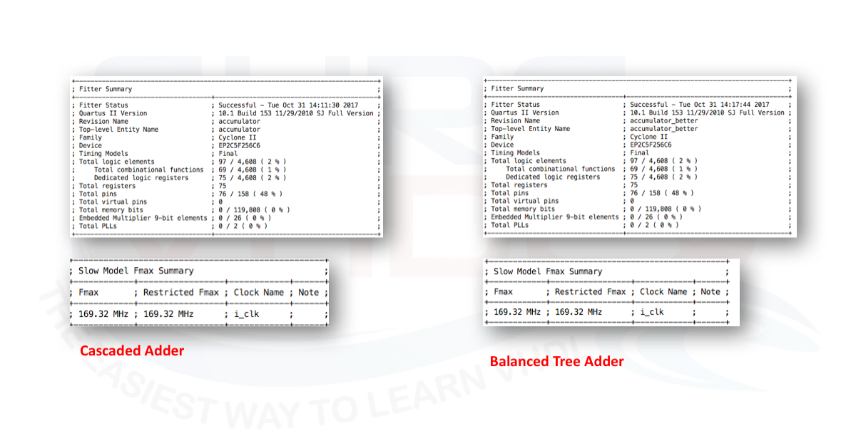
Figure 6 Quartus II area and timing report summary for Cyclone II
Xilinx ISE Implementation
Xilinx ISE implements the different VHDL descriptions of the adder in a slightly different way and the implementation depends on the VHDL RTL code. The FOR-LOOP implementation triggers different hardware architectures. A timing and area report for the two designs is reported in Figure 7.
As clear, on a Xilinx Spartan 3 FPGA, equivalent to the Cyclone II Altera FPGA, the area and timing report for the two different implementations differ both in area and timing. The maximum timing achievable is in the balanced VHDL code version and it is about 80 MHz in the cascaded adder implementation and about 107 MHz in the balanced tree adder implementation.
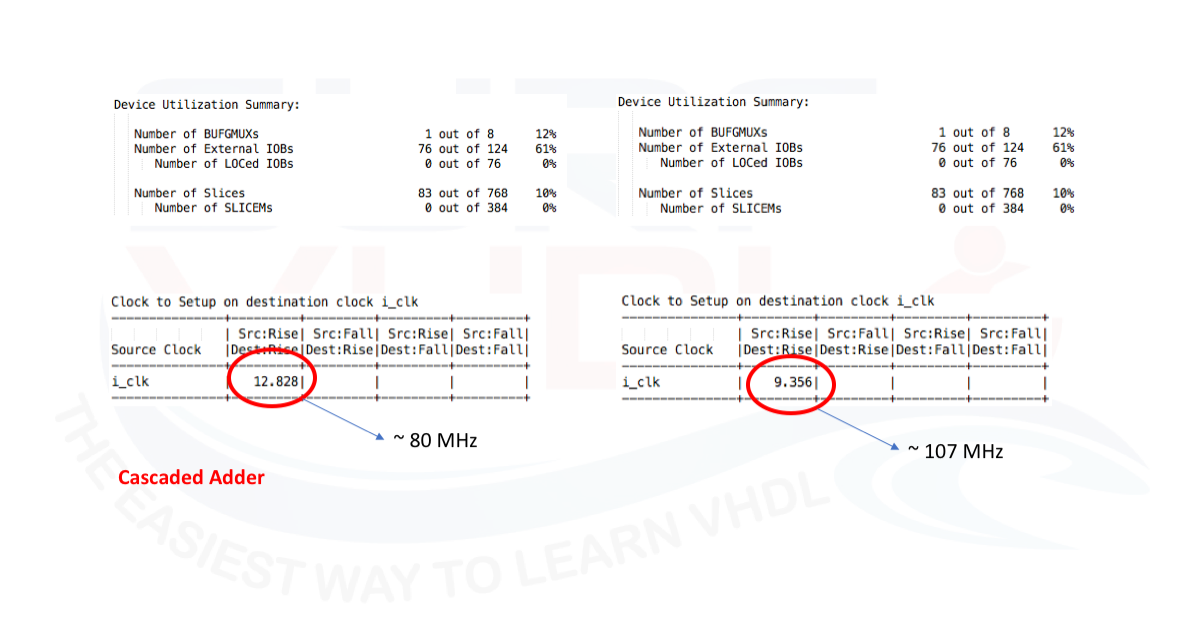
Figure 7 – ISE area and timing report summary for Spartan3
Xilinx vs Altera
In this particular example, Altera Quartus II optimization seems to work better than Xilinx ISE optimization.
It is always a good VHDL design approach to read the layout report such as mapper, fitter and static timing analysis in order to verify if the obtained results are in line with the expected ones.
Conclusion
In this post, we treated the implementation of FOR-LOOP in VHDL. After the VHDL syntax of the FOR-LOOP and its BNF, we tried to understand, in two different examples, the consideration to take into account when dealing with FOR-LOOP VHDL statement.
Last, but not least, the same VHDL code could be translated in different implementations by different synthesizers as we confirmed using Altera Quartus II and Xilinx ISE .
As a design rule, we should write a VHDL code that reflects the hardware architecture we want to realize in order to guide the VHDL synthesizer toward our hardware implementation.
Even if the synthesis software is becoming more and more powerful, we should always check the synthesis and mapping results to verify that our VHDL code has been translated as we expect.
Reference
[1] RTL HARDWARE DESIGN USING VHDL Coding for Efficiency, Portability, and Scalability
[2] VHDL Programming by Example 4th Ed Douglas – Perry
[3] Xilinx ISE