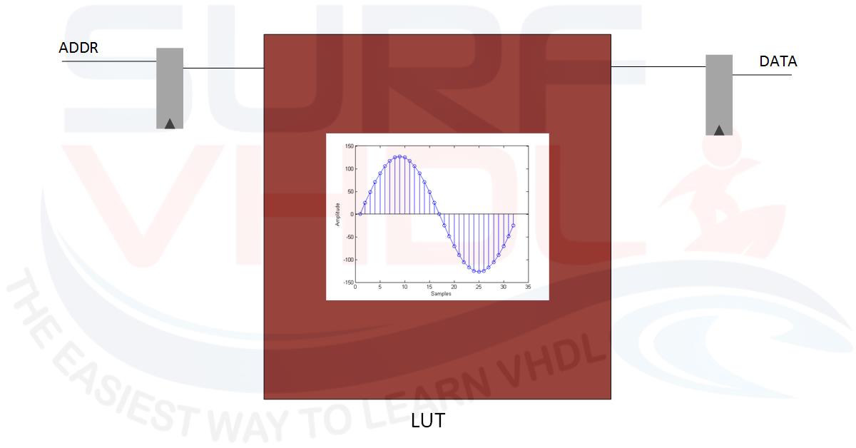
In Digital Signal Processing, often is required the implementation of transcendental math function as trigonometric functions (sine, cosine, tan, atan) or exponential and logarithmic functions and so on. An efficient way, when possible, is to implement an approximation of these functions using Look Up Table or LUT as the sine example in Figure1.
In modern FPGA a large amount of RAM/ROM memory is available, so the LUT implementation requires only FPGA memory hardware resources and few additive registers.
A typical use of LUTs implementing mathematic trigonometric function is the Direct Digital Synthesis (DDS) of sinusoidal tone.
A simple DDS architecture is composed by NCO and LUT as in Figure2
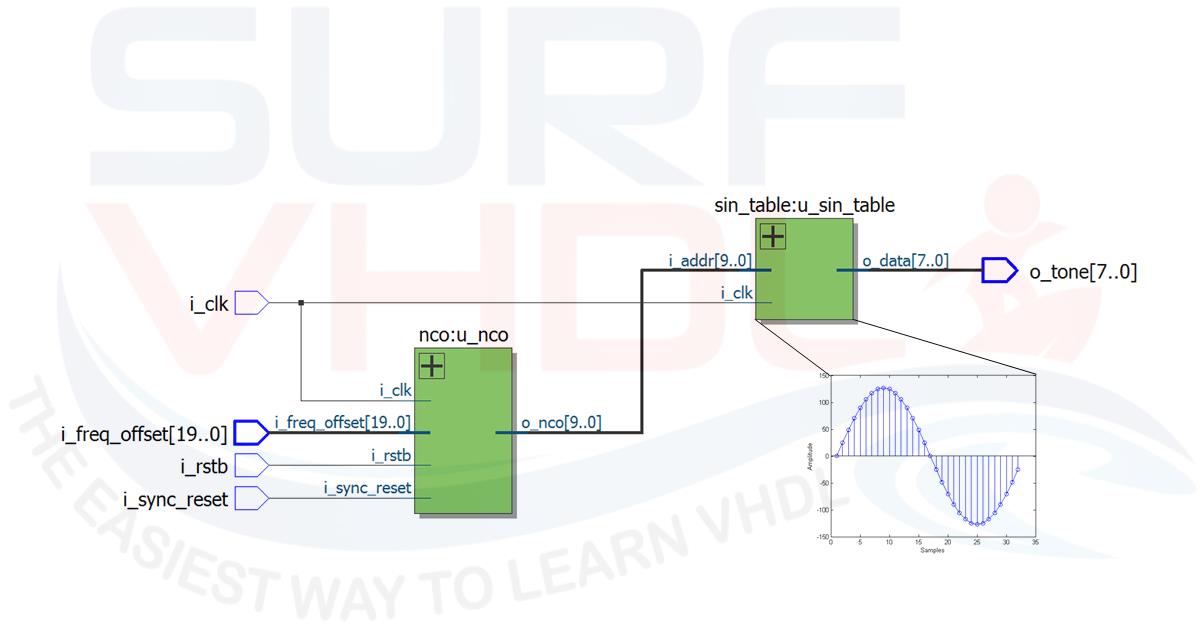
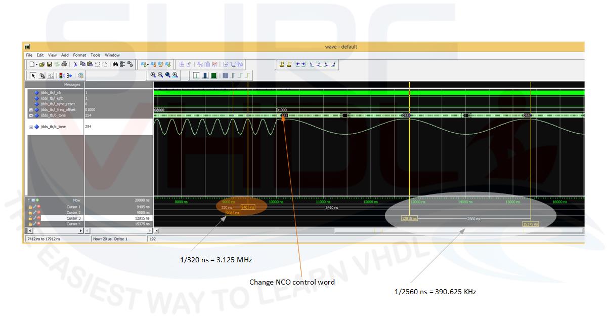
Setting proper NCO frequency word, the output of the LUT generates a tone using the sine samples stored into the LUT.For example, using a system clock of 100 MHz the Figure reports the configuration for a sine wave output frequency of 3.125 MHz with a NCO word 0x08000, and 390.625 KHz after changing NCO frequency word to 0x01000 (3.125 MHz / 8 = 390.625 KHz).
For example, using a system clock of 100 MHz the Figure reports the configuration for a sine wave output frequency of 3.125 MHz with a NCO word 0x08000, and 390.625 KHz after changing NCO frequency word to 0x01000 (3.125 MHz / 8 = 390.625 KHz).
Sine Wave digital samples generation
In this post, we want to focus our attention on LUT sine wave samples generation.
How do we can generate the samples of the sine wave and the LUT?
There are several ways to implement a sine wave LUT:
- using Matlab or equivalent SW
- use C++ to write on file the samples
- use VHDL
As we are Surf-VHDL which could be the way we wish to use? What do you guess?
Maybe Perl 🙂 ?
Ok, let’s see how to generate the samples of a sine wave using VHDL test bench. Of course, the VHDL code for generating a sine wave table is not a synthesizable code. You can use it to generate the sine / cosine wave samples that you will use to create your LUT or ROM component.
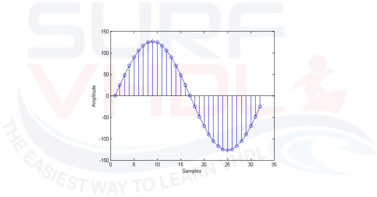
In Figure4 is reported an example of a 32 sine wave samples quantized using 8 bit. The X axis reports the sample and Y axis reports the quantized amplitude.
In other words, we need to generate the quantized version of the following trigonometric sinusoidal function:
sin(2*pi*nT)
where the time vector nT represents the sampling period. If the sampling period is set to one for sake of convenience, and let NS the number of samples of sine wave, let’s define the sampling period as 1/NS
the time vector will be represented:
0, 1/NS, 2/NS,.., (NS-1)/NS
The VHDL is not so friendly as C++ or Matlab if you need to create such sine vector using type real. In fact, VHDL is a hardware description language, but we want to demonstrate that it can be used also for LUT file generation of a sine / cosine wave samples.
Using Matlab a possible simple code for sine wave generation of 32 samples and maximum quantized value of 127 can be the following:
np=32;
A=127;
t=linspace(0,1-1/np,np);
sin_table = (round(sin(2*pi*t)*A))
This code is very simple and compact.
Using VHDL you need few code lines more…
Here below there is an example of a VHDL code generating a sine wave samples and write it to an external file. It is clear that, if you change the transcendent function you can generate the all the LUTs you need. Then you can use the file containing the sine wave samples to create a VHDL ROM file that you can use inside your design, for example, the DDS implementation of Figure2 above.
The sine amplitude is defined as 2^nbit = 256 quantized level (nbit = 8). If the representation is signed the sine wave amplitude samples will have the range -128 to +127, if the representation is unsigned the sine wave amplitude samples will have the range 0 to 255.
The number of the samples are configurable as 2^nsamples = 32
The values of the sine wave table are generated using the quantization_sgn VHDL function. In this function, the test on the positive or negative number is performed. In fact, for positive number the maximum possible value is 2^(NB-1)-1; for negative number the minimum possible value is -2^(NB-1) where NB is the number of quantization bit.
In order to perform rounding before performing the truncation, the floating point value of 0.49 is added (line 24 and 26). This value is 0.49 not 0.5 as could be added for example using C++, because VHDL truncation of 0.5 returns 1, not 0. The quantization of sine function as unsigned value if performed by the quantization_uns function that simply recall the quantization_sgn with the same parameter and return the value as unsigned simply adding 2^(N-1). The sum is performed by the XOR function on the sign bit.
If you need to review the 2’complement representation of a binary number, click here.
library ieee;
use ieee.std_logic_1164.all;
use ieee.numeric_std.all;
use ieee.math_real.all;
library std;
use ieee.std_logic_textio.all;
use std.textio.all;

entity write_table is
end write_table;

architecture behav of write_table is

function quantization_sgn(nbit : integer; max_abs : real; dval : real) return std_logic_vector is
variable temp    : std_logic_vector(nbit-1 downto 0):=(others=>'0');
constant scale   : real :=(2.0**(real(nbit-1)))/max_abs;
constant minq    : integer := -(2**(nbit-1));
constant maxq    : integer := +(2**(nbit-1))-1;
variable itemp   : integer := 0;

begin
  if(nbit>0) then
    if (dval>=0.0) then
      itemp := +(integer(+dval*scale+0.49));
    else
      itemp := -(integer(-dval*scale+0.49));
    end if;
    if(itemp<minq) then itemp := minq; end if;
    if(itemp>maxq) then itemp := maxq; end if;
  end if;
  temp := std_logic_vector(to_signed(itemp,nbit));
  return temp;
end quantization_sgn;

function quantization_uns(nbit : integer; max_abs : real; dval : real) return std_logic_vector is
variable temp        : std_logic_vector(nbit-1 downto 0):=(others=>'0');
constant bit_sign    : std_logic_vector(nbit-1 downto 0):=('1',others=>'0');

begin
  temp := quantization_sgn(nbit, max_abs, dval);
  temp := temp xor bit_sign;
  return temp;
end quantization_uns;

constant nsamples  : integer:=5;  -- LOG2 OF THE VALUE
constant nbit      : integer:=8;
constant step      : real := 1.00/real(2**nsamples);

signal clk         : std_logic:='0';
signal sine        : real:=0.0;
signal qsine_sgn   : std_logic_vector(nbit-1 downto 0):=(others=>'0');
signal qsine_uns   : std_logic_vector(nbit-1 downto 0):=(others=>'0');

begin

clk  <= not clk after 1 ns; -- only for wave visualization on modelsim

p_sine_table : process(clk)

file test_vector                       : text open write_mode is "sin_table.dat";
variable row                           : line;
variable count                         : integer :=0;

variable v_sine        : real:=0.0;
variable v_tstep       : real:=0.0;
variable v_qsine_uns   : std_logic_vector(nbit-1 downto 0):=(others=>'0');
variable v_qsine_sgn   : std_logic_vector(nbit-1 downto 0):=(others=>'0');

begin
  if(rising_edge(clk)) then
    -- write table
    if(count<(2**nsamples)) then

      v_sine  := sin(MATH_2_PI*v_tstep);
      v_qsine_uns := quantization_uns(nbit, 1.0,v_sine);
      v_qsine_sgn := quantization_sgn(nbit, 1.0,v_sine);
      v_tstep := v_tstep + step;

      write(row,to_integer(unsigned(v_qsine_uns)), right, 5);
      write(row,',');

      count := count + 1;

      if((count mod 16)=0) then
        writeline(test_vector,row);
      end if;  -- write 16 values per line

      sine  <= v_sine ;
      qsine_uns <= v_qsine_uns;
      qsine_sgn <= v_qsine_sgn;
    else
      assert false
      report "Table Generated"
      severity failure;
    end if;
  end if;
end process p_sine_table;

end behav;
The process “p_sine_table” is used to write the sine samples to the file “sine_table.dat” below:
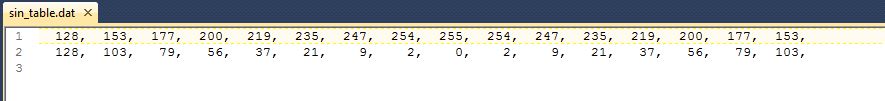
It is worth of notice that in this example we are using a fake or artificial clock only to allow the plot of the sine wave samples on the Modelsim simulation wave of Figure5.
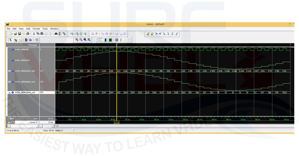
Line 84 print to file the sine samples as 16 columns per row integer separated by a comma, so you can easy generate the ROM code for a sine waveform as Figure5. Here an example of how to use the sine samples to write the code of a ROM containing the sine values. The ROM address is 5 bit, 32 ROM location and data is represented as 8-bit unsinged value:
library ieee;
use ieee.std_logic_1164.all;
use ieee.numeric_std.all;

entity sin_table is
port (
  i_clk          : in  std_logic;
  i_addr         : in  std_logic_vector(4 downto 0);
  o_data         : out std_logic_vector(7 downto 0));
end sin_table;

architecture rtl of sin_table is
type t_sin_table is array(0 to 31) of integer range 0 to 255;

constant C_SIN_TABLE  : t_sin_table := (
  128,  153,  177,  200,  219,  235,  247,  254,  255,  254,  247,  235,  219,  200,  177,  153,
  128,  103,   79,   56,   37,   21,    9,    2,    0,    2,    9,   21,   37,   56,   79,  103);

begin

--------------------------------------------------------------------

p_table : process(i_clk)
begin
  if(rising_edge(i_clk)) then
    o_data  <= std_logic_vector(to_unsigned(C_SIN_TABLE(to_integer(unsigned(i_addr))),8));
  end if;
end process p_table;

end rtl;
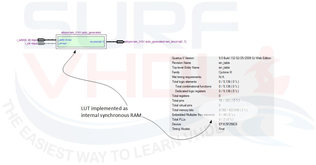
You can use the VHDL code above to generate all the transcendent function you need in your VHDL design simply modifying the function, number of bit for sample and quantization. In figure is reported the RTL view and post-layout report of the VHDL code for 1024 samples 8-bit data sine ROM, using Altera Quartus II
If you appreciated this post, please help us to share it with your friend.
[social_sharing style=”style-7″ fb_like_url=”https://surf-vhdl.com/how-to-generate-sine-samples-in-vhdl” fb_color=”light” fb_lang=”en_US” fb_text=”like” fb_button_text=”Share” tw_lang=”en” tw_url=”https://surf-vhdl.com/how-to-generate-sine-samples-in-vhdl” tw_button_text=”Share” g_url=”https://surf-vhdl.com/how-to-generate-sine-samples-in-vhdl” g_lang=”en-GB” g_button_text=”Share” linkedin_url=”https://surf-vhdl.com/how-to-generate-sine-samples-in-vhdl” linkedin_lang=”en_US” alignment=”center”]
If you need to contact us, please write to: surf.vhdl@gmail.com
We appreciate any of your comment, please post below:
I am having a difficult time following the flow of the first VHDL code.
The second part in Figure 5 is pretty easy to follow. I think the first section is trying to take in samples of a file to create a sine wave table and store the samples in the respective ROM locations? Is there a way to break this down into block diagrams so that it can be easier understood? I understand block diagrams easier than the declarations etc. within VHDL. Thank you.
Hi James,
the implementation is straight forward in the VHDL code below Figure 5. It implements the ROM with sine samples.
You ca think about a table:
addr data
0 => 128
1 => 153
2 => 177
and so on…
Great article !!! I have to read all of them, bookmark added 🙂
Thank You!
i tried running the same code in vivado, i have a doubt, what do i need to give as an input to i_clk and i_addr.
Thanks in advance
i_clk is the clock you are using into your design. The SIN Table is a synchronous ROM.
The “i_addr” is the ROM address
What do we have to give as an input for i_clk and i_addr?
really good article ,clearly explained…good job @surf-vhdl …
thank you Farath!
Hello here,
thank you for this paper,
Please can I find something about NCO because now I am working it.
I have to add an IP core DDS on my projet and LUT_Sine
Or write my own program for all of them (program of NCO and LUT_Sine )
I need your hepls !!
https://surf-vhdl.com/how-to-implement-nco-vhdl/
ciao
Wawouu !
I’am verry to you , now I’am going to read it
I will share with you my point of view
See you soon !!
thank you verry much!
I’ve got the following error:
Warning (10036): Verilog HDL or VHDL warning (50): object “sine” assigned a value but never read
you did not assign the signal to any output, the tool will simplify the netlist
Is there any example where I can generate a timing system using a counter to use CORDIC library. For example, I want to generate (x,y) points from (cost(at,bt) , sin(at,bt)) where t is the timer and A,B are any int value.
“t” could be the phase of CORDIC
A, B could be the input
n order to perform rounding before performing the truncation, the floating point value of 0.49 is added (line 24 and 26)
how can I do it using Fixed point?,
Did you have any program, tip or idea to answer my question, please?
in the post there is the Matlab code for fixed point generation of the sine samples
hello here,
thank you for this articel.
i’ve got following error :
Warning (10036): Verilog HDL or VHDL warning at write_table.vhd(49): object “sine” assigned a value but never read
and then i’ve message error :
Error (10414): VHDL Unsupported Feature error at write_table.vhd(49): cannot synthesize non-constant real objects or values
can you help me to solve this problem ?
thank you
Entity “write_table” is used to generate the sin sample. It isn’t synthesizable.
You must use something like entity “sin_table”
I mis understand about this problem. Please, help me 🙁
which problem?
When i start compilation i get an error like this: “cannot synthesize non-constant real objects or values”
And i can not simulate this codes. Could you show or explain to me how to simulate ? I couldnt generated samples ? How can i generate ? I will use this generator into my modulator project for my thesis. So i need a help..
Thank you
Can I have test bench please ?
Best Regards
Hello ,
I can not simulate this codes. Could you show or explain to me how to simulate ? I couldnt generated samples ? How can i generate ?
Thanks
what is your problem?
Hi SURF-VHDL!
First of all, thanks for putting together this material. I’m working on a customized PWM IP core that requires a sine wave in .dat format. I am familiar with Vivado and its tools but I’m still a junior and wasn’t aware of this method being possible in VHDL. Now my problem is that I can’t infer from your explanation here how to genereate the sin_table.dat file you indicate in your code. How do I generate that .dat file so I can add it as a source for my PWM IP core?
Please let me know.
Cheers!
Diego
you can use the either the VHDL code or the matlab code
Hi, thank you for this code.
Do you happen to have the code for UART Tx and Rx through a USB to UART interface?
Yes, it is part of my VHDL syntax course:
https://surf-vhdl.teachable.com/p/start-learning-vhdl-using-fpga
Hello, thank you for this code. But I do have some questions.
1-Can I have the test bench to have a continuous loop ?
2-Do you know whether this code is compatible with Artix 7 ?